until now I did work wit ESP9266-01 and ESP8266-12, with Arduino ESP8266 IDE and NodeMCU, and pretty much ignored adding any capacitators to my ESPs althouch I did control a micromotor directly without motor controller before.
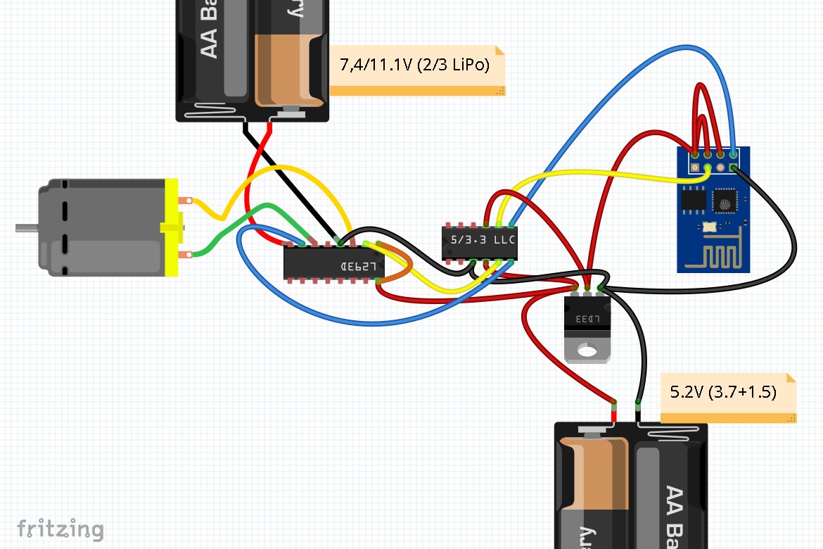
Below you can find Fritzing diagram of my setup:
- * LD33V gives me 3.3V for ESP8266-01 from 5.2V.
* Logic Level Converter (LLC) converts the 3.3V signals from ESP8266-01 to 5V for motor controller L293D
* TXD and GPIO0 signals from ESP8266-01 control Input1 and Input2 of L293D
* PWM pin Enable1 is connected to 5.2V fixed (orange)
If I run this with 3.7V or 7.4V (1/2 LiPos) all is fine, I can reliable telnet over Wifi into ESP8266 NodeMCU, set both lines to output by gpio.mode(x,gpio.OUTPUT) [x=3 or x=10] and then toggle the lines by gpio.write(x,1-gpio.read(x)). It allows me to start the motor and stop the motor, with rotation in the direction I selected. Slow with 3.7V (its a 9-15V motor), quite some speed with 7.4V.
Now if I put third Lipo in play to get 11.1V motor voltage, the motor keeps running but after some seconds resets the ESP8266-01 and I have to pull power to get it stopped.
Things get worse if I control Enable1 via ESP8266-01 line and set Input1 to 5V. This works with 3.7V (but only on/off via digitalWrite, PWM seems to have no effect on speed). If I connect 2nd Lipo to get 7.4V the motor starts very fast and then resets ESP8266-01 before I even have a chance to copy in the toggle command into telnet session for turning off.
So my questions are:
- Where do I have to add capacitators to make ESP8266-01 immune to motor spikes?
What else needs to be added to diagram?

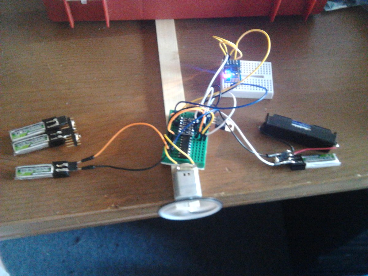
Photo from yesterday:

Hermann.
