- Sat Dec 26, 2015 8:45 am
#37154
Roypo wrote:So I got myself a yellow test board
/--snip--/
But I am really stuck,
I can connect it directly by http://192.168.4.1/config?command=light and others command but can not flash a new framework??!?!!
It is connected to power source (3XAA),
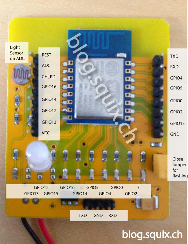
I connected c232HD-EDHSP-0 (USB to UART Serial) to GND , RXD and TXD PINs (black,yellow,orange) ,
Closed the jumper for flashing , but that is about it
All my effort to connect via serial just won’t work…
Can someone help me ?
A dummies guide to flash new frame work… please!
The guide I found are not helping in this case
Thanks,
It would be helpful to see a diagram of how you have it hooked up for flashing and what you have tried to flash onto the chip. I have used that board with the ArduinoIDE without too much trouble and I posted a "review" here
viewtopic.php?f=29&t=5503 that you might find helpful.
As I said in that post, I found two caveats:
"The board will operate on three AA batteries, but I found this problematic for doing a lot of flashing (rechargeable ones draining too quickly). For my investigation, I connected a reliable 5v supply to the battery case after removing the batteries. During final testing, I did use batteries." IOW, don't bang your head against the wall when you don't have enough power going in. Since that board has a regulator, attaching a good +5v power supply (500 mA or more) instead of the batteries will save you a lot of guessing.
If I am reading the datasheet for your USB/Serial board correctly, the EDHSP looks like it is putting out 5V at 200 mA and that is probably insufficient (It does look like the I/O pins are 3.3v so that is good). I would not use it to power the board.
"The TXD GND RXD pins on the front of the ESP board (not the pins nearest to the chip) are straight through to the USB-serial board, not the usual TX->RX and RX-TX. I used this
http://www.dxsoul.com/product/jy-mcu-us ... duiyMuFO4Q USB-serial board and installed a 3v jumper and then verified that all relevant signals were at 3v. " You will not be able to flash the chip if you have the serial port connection wrong - I was so used to reversing these when using a USB->Serial board (i.e. TX->RX and RX->TX) that it took me awhile to figure this out and did so when I tested the TX/RX pins that are right next to the chip pins (which can be connected to the USB/Serial board with TX->RX and RX->TX) instead of the three pins on the board edge. If I am understanding your post, it looks like you may have those lines hooked up correctly, but it is worth checking.
I use the ArduinoIDE and had no trouble flashing the board as it is flashed with the ArduinoIDE framework" when you upload the program. I included a little board exerciser program in my post that could be used for testing.
Hope this helps and let us know how it goes,
Cheers,
DrG
