WiFiAnalog/Digital Control Module , MQTT, SP-12
Full description of this project at http://www.horaciobouzas.com
WiFi Analog/Digital Module reads analog or digital data, returns the values and responds according to programmable limits. MQTT protocol
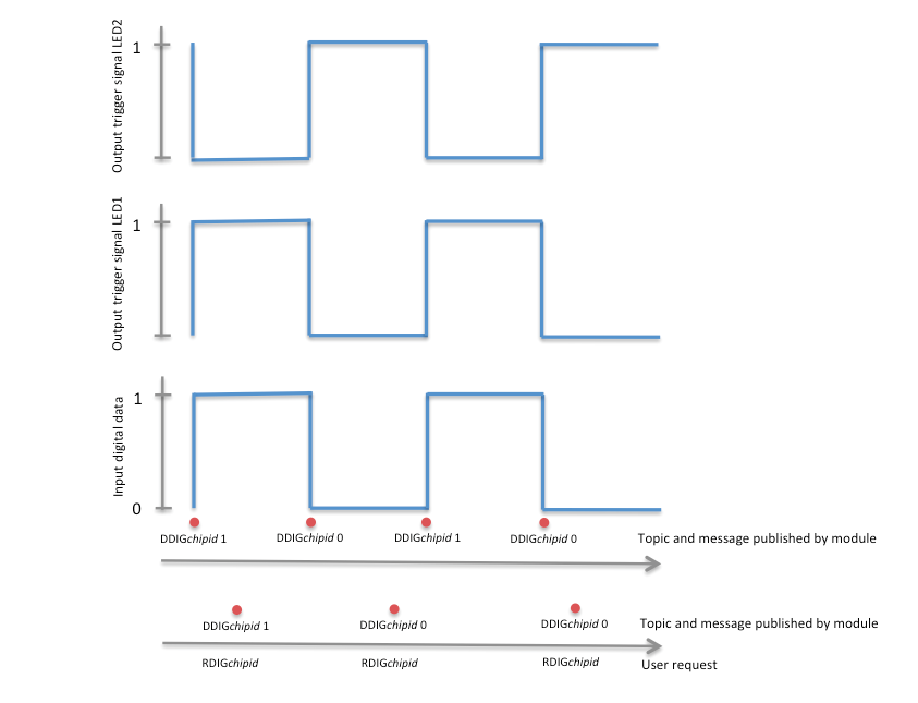
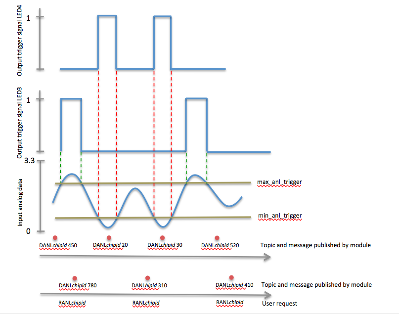
The analog/digital control module reads analog data and digital data through its 2 input terminals. Input analog data limits are zero VDC to 3.3VDC, and this maps into output values of 0 to 1024 Input digital data limits are zero, for a digital zero, and 3.3VDC for a digital 1 The module sends the value of the measured analog data periodically every Interval milliseconds, and it sends the value of the measured digital data when this chances from 0 to 1 or from 1 to 0. The user can also request the module to send the measured values of analog and/or digital data at any time by publishing a specific MQTT topic. The module provides a triggering signal whenever the digital data changes (Figure 1) The module provides a triggering signal when the analog signal is less than a preset value or larger than a preset value (Figure 2)
Figure 1: Digital data response

Figure 2: Analog data response

Once the module is connected to the WiFi router it will stablish communication with the MQTT server and port as specified above and will attempt to connect. Wait a few seconds and all 4 LEDs will blink in sequence indicating a successful connection. If this fails, reset the board and wait a few seconds for the LED sequence. The module uses MQTT protocol for communication. MQTT topics are composed of a four letter acronym followed by the ESP822 chipid (the chipid is listed with your documentation), XXXXchipid Once a connection with the MQTT sever is established, the module is ready for communication and therefore reading analog and digital data and sending commands.
A typical MQTT instruction is composed of a topic followed by a message.
MQTT Topics and Messages
Note that the analog value is sent by the module at regular intervals (controlled by the value of Interval_in_milliseconds) as specified during configuration or changed during operation, while the digital value is sent only when it changes. You can always request the analog or digital value at any time by publishing the respective topic.
WiFi Analog/Digital Module reads analog or digital data, returns the values and responds according to programmable limits. MQTT protocol
The analog/digital control module reads analog data and digital data through its 2 input terminals. Input analog data limits are zero VDC to 3.3VDC, and this maps into output values of 0 to 1024 Input digital data limits are zero, for a digital zero, and 3.3VDC for a digital 1 The module sends the value of the measured analog data periodically every Interval milliseconds, and it sends the value of the measured digital data when this chances from 0 to 1 or from 1 to 0. The user can also request the module to send the measured values of analog and/or digital data at any time by publishing a specific MQTT topic. The module provides a triggering signal whenever the digital data changes (Figure 1) The module provides a triggering signal when the analog signal is less than a preset value or larger than a preset value (Figure 2)
Figure 1: Digital data response

Figure 2: Analog data response

Once the module is connected to the WiFi router it will stablish communication with the MQTT server and port as specified above and will attempt to connect. Wait a few seconds and all 4 LEDs will blink in sequence indicating a successful connection. If this fails, reset the board and wait a few seconds for the LED sequence. The module uses MQTT protocol for communication. MQTT topics are composed of a four letter acronym followed by the ESP822 chipid (the chipid is listed with your documentation), XXXXchipid Once a connection with the MQTT sever is established, the module is ready for communication and therefore reading analog and digital data and sending commands.
A typical MQTT instruction is composed of a topic followed by a message.
MQTT Topics and Messages
- RANLchipid : this topic instructs the module to read a sample of the analog data and send it back via an MQTT topic and message. The module in response sends a topic and value as follows:
DANLchipid value ; you can get the analog value by subscribing to the topic DANLchipid and getting the value from the message
RDIGchipid : this topic instructs the module to read a sample of the digital data and send it back via an MQTT topic with the value as a message. The module in response sends a topic and value as follows:
RANLchipid value ; you can get the digital value by subscribing to the topic RANLchipid and getting the value from the message
MANLchipid min_analog_trigger (min 0, max 1024, def 300): this topic allows the user to set the module’s minimum analog value used for triggering the LED and signal . The change takes immediate effect.
XANLchipid max_analog_trigger (min 0, max 1024, def 800):: this topic allows the user to set the module’s maximum analog value used for triggering the LED and signal. The change takes immediate effect.
INTEchipid Interval_in_milliseconds (min 500 ms, max 240000 ms, def 5000 ms): this topic allows the user to set a new interval in milliseconds for receiving analog data. The change takes immediate effect.
RESTchipid: this topic allows the user to reset the module remotely.
Note that the analog value is sent by the module at regular intervals (controlled by the value of Interval_in_milliseconds) as specified during configuration or changed during operation, while the digital value is sent only when it changes. You can always request the analog or digital value at any time by publishing the respective topic.