- Sat Nov 12, 2016 6:50 pm
#58058
Development boards do not typically have any protection because the person using it should decide what needs to be added. The assumption with a development board is that all connections will be local. Also with hobbyist targeted boards they only put in what they have to. They will cut corners wherever they can to save a couple of pennies. But then again the cost of this stuff is so low it isn't a big deal replacing it when it blows up. As long as you don't factor the time you spend doing it.
There are some good mosfets that will operate properly with a three volt logic level. And as far as the resistor value for the base resistor I tend to want more than enough current rather than just enough. If you consider that 5 mA and higher is typically used for driving leds then you should not be worried about driving that level of current into the base of the transistors. Either way, it's no big deal. Just make sure you have enough to drive the transistors into saturation at the coldest temperature that they will experience.
EDIT:
I looked over the board layout. It is better than some that I have seen here. It still could be better. I don't feel like explaining too much as I want to get to some real work. But some of what I would change is getting the area on the sides of the antenna clear of copper. You could have moved the lower relay to the right. The switch connection probably could have fit more to the right. I don't know if you plan on using a pcb mounted switch. It looks like there will be wires soldered to the board but maybe not.
I don't like how your ground snakes through the board. It is much better if you reduced the size of the current loops. Current loops are the areas between the outgoing signal and the return path. If that doesn't make sense to you then Google it. You are using a single sided board and that makes things tougher. But there is no reason that you can't use wire or 0 Ohm resistors to make connections across the board. If you have the space then use it the best way possible.
You have flooded areas that I expect you hope will form a ground plain. The problem is that it doesn't do anything useful (any more than the original trace) if there is no path to somewhere. An example of what I mean is the ground area to the left of the ground connection on the module. The triangular area. There is no reason for current to go there and because of that it does nothing. But it doesn't normally hurt anything so I won't make a big deal over it.
On relay 2 I would swap the connections on the switch. That way you would not have to have the trace between the AC pin contact and the DC trace. You would be able to use thicker traces and also have more distance between the low voltage circuitry and the high voltage.
One more EDIT
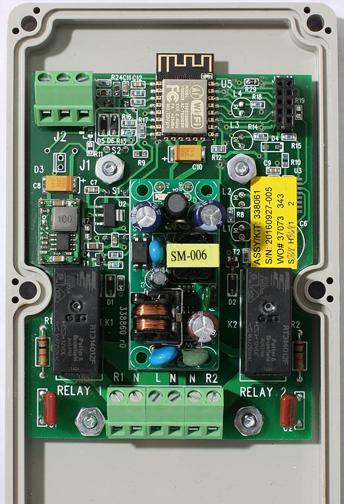
Your board reminded me of a board I did for my work a few months ago. I have one at home that I was testing out. Like your's it has two relays on each side of the power supply. Each relay is connected to the line side. No switch like your's. I wanted to show you what I do with the antenna area. I hang it off the board. No components, no traces, not even blank board under it. According to Expressif this will perform the best of the options they tried.

There are two push button switches on the other side of the board along with 4 leds. Two connected to the relays. On the top right is a programming connector that can also accept a daughter board that has a 8 pin PIC cpu for a couple of analog inputs. That is what I have so far but other expansion is possible. Below that connector is where a real time clock and super cap can be populated. (under the label) Some of our products go where there isn't reliable internet so we have that as a time option.
The green connector the top left of the board is the analog input. Three terminals so that we can connect a variable pot for position feedback for actuator control. Ot it can also be used as a temperature input. There are a number of different options depending on how the board is populated.
Because we use a lot of 12 volt relays that is what I had populated in the board along with a 12 volt power supply. A cheap switcher board converts it down to 5 volts. A linear regulator is used to go from 5 to 3.3 volts. I can also use a AC to 5 volt supply and eliminate the dc to dc switcher but then I would need 5 volt relays. I have a couple of boards built that way. The relays are rated for 1 hp at 230 volts and 115v. A lot of our products are controlling motors.
This board is the first in a distributed control system. Or it will be shortly. We have been too busy on other projects and will finally get to this one in a couple of weeks.
