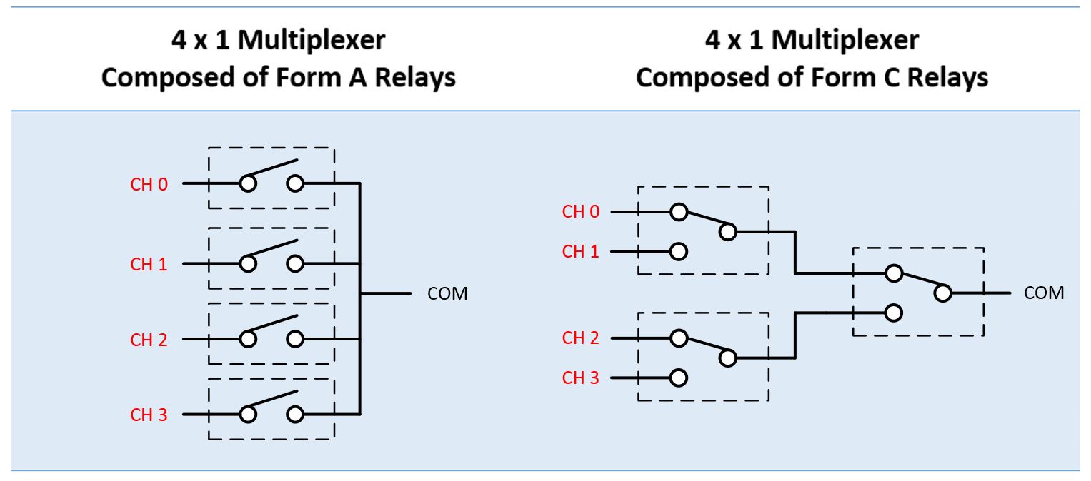
Use relays with both Normally Open and Normally Closed contacts. (along with the Common terminal)
Look at the schematic on the right side.

Assume these are the relay states when the coils are not energized. (not on) The incoming power would connect to COM. The motor windings would connect to CH1, CH2, and CH3. CH0 would be the off path with no motor connection.
All the top connections of the relays are the Normally Closed contact NC. The bottom position is the Normally Open contact NO.
Turning on the top left relay would be the first stage, providing power to CH1.
With the above relay on, and then turning on the right relay, this would apply power to CH2. The second stage.
Turning on the remaining bottom left relay (along with the one on the right) would apply power to CH3, the third stage.
Easy

Now that is how to accomplish the relay staging. What you also should know is that the Normally Open contact on power relays is typically not rated as high as the Normally Open contact.
The normally open contact has the coil pulling the contacts closed. (when the power is applied to the coil) With the Normally Closed contact the internal spring is what is closing the contacts and it doesn't have the same force as the Normally Open contact would have.
For example a relay with a 1/2 horsepower rating for the Normally Open contact might only be rated for 1/3 horsepower for the Normally Closed contact. So look closely at the ratings. And use only horsepower ratings, or other motor ratings. Not resistive load current ratings. For example a 10 Amp relay might only be rated for 1/4 hp at 120 volts.
