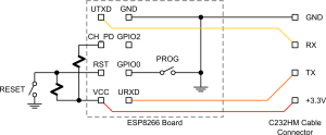
Conflict in Boot modes GPIO2
From here comes https://github.com/esp8266/esp8266-wiki ... ot-Process
And from wiki/doku.php?id=getting-started-with-the-esp8266
It shows GPIO2 floating and I can confirm this definately works .

Can anyone else define where that pin should be and why please. It appears that both might work and maybe the truth table should be ammended to "x" floating ?
or perhaps there is a difference here between NodeMCU/Lua and ESP8266/Arduino setups .
Perhaps there are differences in the firmware that comes with the chip.
There is also the truth table for Olimex boards which shows the positions for jumpers as such https://www.olimex.com/Products/IoT/ESP8266-EVB/
The positions for the all the modes are printed on the board itself. The
table looks like this:
MODE/JUMPER.....TD0JP(MTDO) IO0JP(GPIO0) IO2JP(GPIO2)
SDIO...........................1 ...................x....................x
UART...........................0....................0....................1
FLASH (DEFAULT)........ 0 ...................1................... 1
This is the same as the Expresif table
For example:
Initially, you can't update the firmware of MOD-WIFI-ESP8266-DEV since by
the board starts in the default FLASH mode. In order to update the
firmware of the board you would need to change the starting mode to UART.
This is done by changing the position of the jumper named IO0JP(GPIO0) to
0. After the update is done – change the position of IO0JP(GPIO0) back to
1 again.
So is this "Firmware " the bootloader on the chip (ie version 0.9.5)or is this the program you put on it? Program HEX?
While you are at it "What is the UART Mode specifically used for ?"
What happens when it boots from Flash . Does it start at a particular memory address and run from there or does it start from the first memory address and run right through?
What happens when it boots from UART, again where in memory does it start
Likewise for SDIO mode ,Where does that start from and end and is this meant to read from an SD card or not?
ESP Boot Modes
The Espressif code can boot in different modes, selected on power-up based on GPIO pin levels. (MTDO is equivalent to GPIO15).
GPIO15......GPIO0...... GPIO2...... Mode........Description
L..................L..............H..........UART..............Download code from UART
L..................H..............H.........Flash..............Boot from SPI Flash
H..................x..............x...........SDIO..............Boot from SD-card
In the bootup message 'boot mode:(x,y)' three low bits of x are {GPIO15, GPIO0, GPIO2}.
And from wiki/doku.php?id=getting-started-with-the-esp8266
It shows GPIO2 floating and I can confirm this definately works .

Can anyone else define where that pin should be and why please. It appears that both might work and maybe the truth table should be ammended to "x" floating ?
or perhaps there is a difference here between NodeMCU/Lua and ESP8266/Arduino setups .
Perhaps there are differences in the firmware that comes with the chip.
There is also the truth table for Olimex boards which shows the positions for jumpers as such https://www.olimex.com/Products/IoT/ESP8266-EVB/
The positions for the all the modes are printed on the board itself. The
table looks like this:
MODE/JUMPER.....TD0JP(MTDO) IO0JP(GPIO0) IO2JP(GPIO2)
SDIO...........................1 ...................x....................x
UART...........................0....................0....................1
FLASH (DEFAULT)........ 0 ...................1................... 1
This is the same as the Expresif table
For example:
Initially, you can't update the firmware of MOD-WIFI-ESP8266-DEV since by
the board starts in the default FLASH mode. In order to update the
firmware of the board you would need to change the starting mode to UART.
This is done by changing the position of the jumper named IO0JP(GPIO0) to
0. After the update is done – change the position of IO0JP(GPIO0) back to
1 again.
So is this "Firmware " the bootloader on the chip (ie version 0.9.5)or is this the program you put on it? Program HEX?
While you are at it "What is the UART Mode specifically used for ?"
What happens when it boots from Flash . Does it start at a particular memory address and run from there or does it start from the first memory address and run right through?
What happens when it boots from UART, again where in memory does it start
Likewise for SDIO mode ,Where does that start from and end and is this meant to read from an SD card or not?