-->
Page 1 of 1

ESP8266 uses PWM and H-Bridge to drive a DC motor

PostPosted: Tue Apr 04, 2017 7:20 pm
by RiseNRG


This was an interesting project, I hit a road block at first where the PWM signal wasn't able to turn the motor. I think this is because the PWM pulse frequency which is set at 1000 HZ by default was not allowing enough current to enter the motor for it to commence rotation.

Lowering this to 1 HZ resolved the issue but introduced a noticeable click, I increased it to 10 HZ and there clicking was almost indistinguishable from the sound of a normal motor running. I bumped it up to 50Hz and there speed of the motor dropped significantly.

It seams that PWM can slow a motor based on it's pulse width and also the frequency of those pulses, I have seen recommendations to add a capacitor across the motor terminals to smooth the current supplied to the motor and help to reduce the variance in sorry based on PWM frequency.
Re: ESP8266 uses PWM and H-Bridge to drive a DC motor

PostPosted: Thu Apr 06, 2017 6:22 pm
by mforcen
As far as I know, high frecuency should not be a problem, and the motor should work fine at 1kHz. The motor acts the same way than a low-pass filter. Does the datasheet of the H-Bridge show any information of the cutoff frecuency of the IC?

Re: ESP8266 uses PWM and H-Bridge to drive a DC motor

PostPosted: Fri Apr 07, 2017 2:23 am
by RiseNRG


This is the first video of the system running over a webserver i have connected to via the ESP8266's Wi-Fi feature.


The system running with 2 motors off battery power instead of the PC Power supply, The speed of the motors has decreased significantly when moving from the 12 Volt rail on the power supply to a 9 Volt Cell.


The system mounted to an aluminium Chasis.

Re: ESP8266 uses PWM and H-Bridge to drive a DC motor

PostPosted: Sat Apr 08, 2017 9:10 pm
by RiseNRG
mforcen wrote:As far as I know, high frecuency should not be a problem, and the motor should work fine at 1kHz. The motor acts the same way than a low-pass filter. Does the datasheet of the H-Bridge show any information of the cutoff frecuency of the IC?


It's a L298N - H-Bridge module

Data Sheet: https://www.sparkfun.com/datasheets/Robotics/L298_H_Bridge.pdf

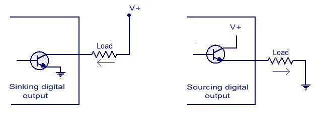
The Source and Sink Currents have turn on and turn off times appear to be in the μS Range. I didn't know this but you can supposedly connect your load in a Sink or Source configuration. Image from circuits today below.

Image

The sink (1.8 μS) configuration appears to be faster at saturating than the source (2.7 μS) configuration.

I believe this means that assuming the saturation time for the motor and on board capacitors are 0 seconds we can run the system at 370 KHz and should see the motor move.