-->
Page 1 of 3

IoT Project ESP12-E

PostPosted: Fri Mar 26, 2021 6:20 pm
by Oscar Fuentes
Good evening, I am doing a project in which I want to measure air quality. I started the project with the ESP8266 NodeMcu board and three sensors, temperature (DHT22), VOC's (CCS811) and PM (PPD42).

I have it all assembled with a breadboard and the NodeMcu and it works fine.

The fact is that I want to pass it to PCB and I am a little lost. From what I've been reading, I have to use the same board but without NodeMcu, so I use ESP12-E.

I have tried to make a design on the web https://easyeda.com/, (I attach images). I copied the connections that I already have working and grouped all the GND connections in a single point.
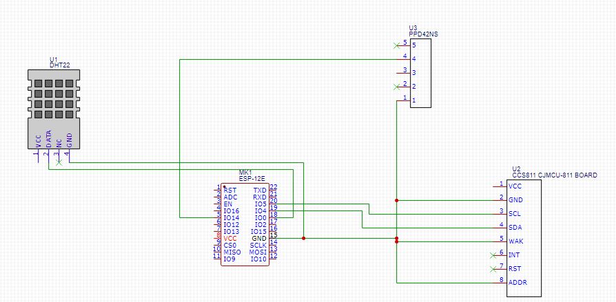
Image

The 3V3 pins I still have no idea how to do it, if anyone can give me a hand I would appreciate it.

Am I wrong or am I on the right track?

Thanks a lot! (::

Re: IoT Project ESP12-E

PostPosted: Sat Mar 27, 2021 5:30 am
by Bonzo
I make my projects on a strip board and have a track for 3V3 and one for 0V. Basically it is like a breadboard and I link all my 3V3 and 0V into that.

Out of interest I moved from the DHT sensors to BMP or SHT as they were more reliable.

You can see one of my projects here: viewtopic.php?f=11&t=19458&start=4 with a ESP-12E and on the first page with a NODEMCU mini.

You will need to find a way to program the ESP-12E before you fix it to the board and after. On the first page I use the micro USB and on the second I have a jumper and FTI pins to do it. On my current project I am going to use OTA and program the board with OTA software before installing.

Re: IoT Project ESP12-E

PostPosted: Sat Mar 27, 2021 7:08 am
by btidey
Note that you have to be careful to ensure that the boot select pins (GPIO2,0,15) are set correctly to allow the module to start up in normal run mode (H,H,L). GPIO15 needs a pull down resistor (e.g. 4k7) to 0V. You have GPIO0 connected to a peripheral so you need to be sure that this starts of high at boot, or use a different pin. GPIO2 and GPIO0 do have weak pull ups enabled at boot so will default high if nothing else is connected; some prefer to add a 10K pull-up on these lines to be sure.

The SCL, SDA lines do need pull up resistors. These may be present on the CCS811 board already but worth checking.

EN needs to high for the module to run at all. It can be connected direct to the VCC 93v3) line or via a pull up resistor.

For the 3v3 you need to know how you are going to power the project. Main choices would be a native 3v3 supply module, a 5V source (e.g.USB) feeding a LDO 3v3 regulator, or a battery (Li-Ion) again feeding a regulator). It's also a good idea to include an extra bypass capacitor across the Vcc / GND lines close to the ESP8266. (e.g. 220uF).

Re: IoT Project ESP12-E

PostPosted: Sat Mar 27, 2021 12:13 pm
by Oscar Fuentes
Good btidey, I am developing the project on the web https://easyeda.com/, can I share the link so you can help me please?

https://easyeda.com/editor#id=|e2df41ec ... 884a1cee1d

I don't know exactly how to do the resistors on the GPIOs.

The project will have a 5v source (probably USB)

Thank you for everything