ESP8266 NodeMCU - PINOUT
Hi,
I have troubles with my project and I need your help!
Setup:
- ESP8266 NodeMCU DevBoard
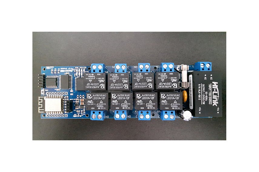
- 8 channel relay module 5V
- 16/2 LCD with IC adapter (SDA/SCL)
I want to use the ESP8266 to control the relay and I also need to show static information on the LCD.
- What is the best pin setup for this project?
I currently use the following:
RELAY1 = GPIO16; // D0
RELAY2 = GPIO10; // SD3
RELAY3 = GPIO0; // D3
RELAY4 = GPIO2; // D4
RELAY5 = GPIO14; // D5
RELAY6 = GPIO12; // D6
RELAY7 = GPIO13; // D7
RELAY8 = GPIO15; // D8
LCD SCL = GPIO5; // D1
LCD SDA = GPIO4; // D2
ESP8266 VIN -> 8CHANRELAY VCC
This works as expected when I do not connect VIN to VCC when the ESP is booting but not if it is.
In this thread: viewtopic.php?f=32&t=11614 @martinayotte says that GPIO15 needs to be pulled down while booting...
I also tried to change GPIO15 to GPIO9 - boot fails also. I also want to use GPIO3 and GPIO1 in the future for SERIAL communication so I don't know what to do..
Thanks!
