Switching relay
I recently created a circuit with a ESP-12 to connect to my doorbell ringer, so that I could perform actions whenever someone pressed the doorbell.
/i/03964/products/2018-06-19T16%3A11%3A55.236Z-DSC03788.JPG)
I now use it to send a MQTT message to home assistant, which in turn takes a snapshot with the camera next to the door, sends the picture via pushbullet to my phone and also sound the wireless door ringer. Great fun, and it works like a charm
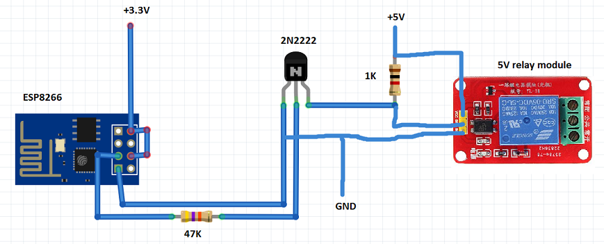
Now I came up with another idea to improve the circuit: I would like to connect a relay to one of the gpio pins of the ESP, so that I can also switch the regular bell on and off, for instance to turn it off during the night.
Fot that purpose I bought a Songle SRD-03VDC-SL-C relay (like these: https://www.aliexpress.com/item/5PCS-lo ... autifyAB=0). Since they're meant to be used with 3V DC I thought I could just use them right away. I tested them with a breadbord adapter at 3v (like one of these: https://www.aliexpress.com/item/Breadbo ... autifyAB=0), and it worked, so I figured it would also work if i connected it to a ESP8366 GPIO and ground.
I tried it with this code:
but it seems that it doesn't work. Googling around, I found lots of similar issues, it seems the ESP pin cannot provide enough power to trigger the relay. I also saw lots of solutions that introduced a 5v source for the relay, but since I have a 3V relay, it seems to me that it would be unnecessary (I also don't have a 5v source in my circuit and I would like to keep the parts count as low as possible).
Any idea how I could solve this problem?
I now use it to send a MQTT message to home assistant, which in turn takes a snapshot with the camera next to the door, sends the picture via pushbullet to my phone and also sound the wireless door ringer. Great fun, and it works like a charm
Now I came up with another idea to improve the circuit: I would like to connect a relay to one of the gpio pins of the ESP, so that I can also switch the regular bell on and off, for instance to turn it off during the night.
Fot that purpose I bought a Songle SRD-03VDC-SL-C relay (like these: https://www.aliexpress.com/item/5PCS-lo ... autifyAB=0). Since they're meant to be used with 3V DC I thought I could just use them right away. I tested them with a breadbord adapter at 3v (like one of these: https://www.aliexpress.com/item/Breadbo ... autifyAB=0), and it worked, so I figured it would also work if i connected it to a ESP8366 GPIO and ground.
I tried it with this code:
Code: Select all
void setup()   {
  Serial.begin(115200);
  pinMode(16, OUTPUT);

  }

void loop() {
   Serial.println("off");
   digitalWrite(16,LOW);

   delay(2000);
   Serial.println("on");
   digitalWrite(16,HIGH);
   delay(2000);

}
but it seems that it doesn't work. Googling around, I found lots of similar issues, it seems the ESP pin cannot provide enough power to trigger the relay. I also saw lots of solutions that introduced a 5v source for the relay, but since I have a 3V relay, it seems to me that it would be unnecessary (I also don't have a 5v source in my circuit and I would like to keep the parts count as low as possible).
Any idea how I could solve this problem?