-->
Page 1 of 2

New to ESP8266 - usart

PostPosted: Tue Oct 23, 2018 9:57 am
by SentinelAeon
Hello, i am new to ESP8266 and new to arduino. I am using arduino IDE, ESP8266 d1 mini and usb-serial converter. What i am trying to do is send a single char from my ESP8266 to my usb-serial converter. I connected tx pin on esp8266 and rx pin on my usb-serial converter. Then i wrote this code:

Code: Select allvoid setup() {
  // put your setup code here, to run once: 
  Serial.begin(9600);
}
void loop() {
  // put your main code here, to run repeatedly: 
    Serial.write("a");
    delay(1000);
 
}


This sent letter a to both serialmonitor of Arduino IDE and to my USB-Serial converter. Job well done you could say. But the problem is, i am not sure why it even sent to USB-Serial converter. I didnt define "Serial" anywhere in the code, so as far as i know Serial is a connection betwen ESP8266 and computer. Now my question is this: What code do i need to write to send letter "a" only to USB-Serial converter but NOT to Serial monitor ? I tried hardwareserial, softwareserial, pinmode, etc. but nothing seems to work.

Re: New to ESP8266 - usart

PostPosted: Wed Oct 24, 2018 3:15 am
by QuickFix
Erm... to get things clear:

This is an ESP8266 D1 Mini (well actually it's a Wemos D1 Mini):Image

This board consists of ESP8266 WiFi circuitry (using an ESP-12F) and a serial to USB convertor (using a CH340G).
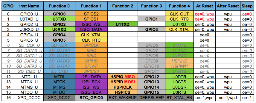
An ESP has two UARTs: UART0 and UART1, UART0 is connected to the USB convertor and in the Arduino core is called "Serial", while for UART1 only the TX-pin is available (on GPIO2) for debug purposes and is called "Serial1" in the Arduino core.

In the Arduino core, you don't have to assign or declare Serial or Serial1, since they already exist; you can directly enable them by issuing ".begin(baudrate)" or don't use them as serial at all, but as GPIO instead (by issuing the pinMode() command).

Do I understand correctly that you attached a separate USB -> serial convertor to the board or aren't' you using a D1 mini to begin with (but, for instance, an ESP-01 instead)?

Re: New to ESP8266 - usart

PostPosted: Wed Oct 24, 2018 1:03 pm
by SentinelAeon
Thank you for your reply, i will try to clear things up. I am using wemos d1 mini. I connected wemos d1 mini to my computer through USB. This is how i upload code to my esp8266. Then i connected my usb-serial module to tx and rx pins on esp8266. This was done purely for testing purposes, later on i will connect stm32F4 and esp8266 through tx and rx pins and they will send data to eachother. Now i have a few questions.

1. Since Serial sends data to both computer and also to USB-Serial module through tx, do i understand correctly that Serial is by default linked to both usb on the esp8266 module and also to tx and rx pins ?

2. I tried creating Serial2 by hardwareserial (HardWare Serial2(0)) and after i did that, tx worked normaly. But when i tried to receive data HardWare Serial2(2), rx didnt work, i didn't get any data. I have to say that when i used default Serial, both tx and rx worked just fine, even without any added resistors. Do you have any idea why ?

3. Question number 2. is purely because i am interested in how esp8266 works. Because Serial works, i will just use that to send data to and from stm32.

Re: New to ESP8266 - usart

PostPosted: Thu Oct 25, 2018 4:26 am
by QuickFix
SentinelAeon wrote:do i understand correctly that Serial is by default linked to both usb on the esp8266 module and also to tx and rx pins ?

In your (Wemos D1 mini) case: yes, the UART of the ESP8266 module is connected directly to the on board USB -> serial convertor AND also available in parallel at the TX- and RX-pins on the side of the board.
An ESP8266 by itself (as a module) doesn't have USB, only serial.

SentinelAeon wrote:HardWare Serial2(2), rx didnt work, i didn't get any data.

What pin did you use for RX?
UART1 doesn't have (an accessible) RX-pin, only TX is available at GPIO2 and was designed to be used for debug purposes only.
There's also an option to fully use UART1 in FUNCTION4-mode, but since the FLASH is connected to GPIO6 - GPIO11, this option can't be used.
You could also swap the UART0 TX(1) and RX(3) pins to GPIO15 and GPIO13 respectively, but I've never seen any real benefit in this myself.

Image