Use this forum to chat about hardware specific topics for the ESP8266 (peripherals, memory, clocks, JTAG, programming)

User avatar
By hundsmiachn
#58070 Hi

First of all thanks for your time looking over my project!

Regarding the clearing of the antenna: I will put the pcb in an enclosure, therefore there is not much room at the top (left of the picture) to move the esp antenna completely out the board, but I think 5mm is possible. And I will remove the rest of the wires blocking the bottom of the antenna, thanks for that...
The space on the lower right is for a switch which I mount into the side of the enclosure, and the pins of the switch need some room, so I wanted to make as much room for the switch and the connections to the pcb as possible. But I think I could really move the relay about 1cm to the right.
Swapping the dc pins on relay 2 is a really good tip, will do that...
This is my first project, and I didn't know extactly how I can modify the ground plane in eagle, I just drew a polygon around the dc part and made an plane out of it, I thought it couldn't hurt and wouldn't waste so much copper (-:
Because I'm etching the board myself at home with the printer method, I tried to make wires as wide as possible and the spaces between as big as possible, so I have some room for error during the process.
I will use the 470R as my base resistor as suggested, dont want to put any more thought into that ;)
Now that I see that there aren't any major flaws in my design, only some minor optimizations, I am really relieved , because it is just a personal project of mine I do in my spare time and don't intent to sell it or something like that. But I will try to implement your input for sure!

On the software side I made a firmware which I can use for all cases. On startup it reads config and time from my webserver in the lan. It can switch 2 relays, 2 servos and switch them on/off according to the temperature reading, or just by app I made, so I can switch my devices with the smartphone. It also has a scheduler, so a relay can be switched on and off at a specific time of day (for my pool pump), or just for a period of time.

thank you for your time !
regards
Erich
User avatar
By rudy
#58075 I just wanted to say that you did a good job on the pcb. Looking it over it reminded me of my earlier stuff from 30 years ago. I have had a few people work with me that also do hardware design and I have always told them to use thicker traces when they can, even on signal lines.

If the pcb had a problem in manufacture a thicker trace would less likely have a complete break. Also if you have to do some soldering or repair then the foil is less likely to lift when it has larger traces attached to it. More important with non plate-through boards. So I liked the width you chose.

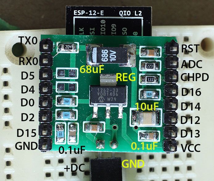
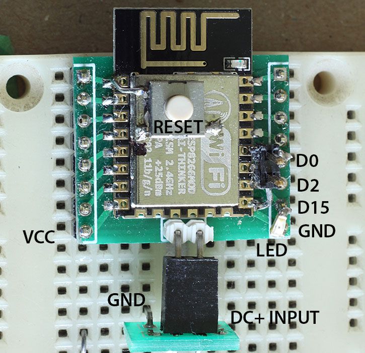
If you have the stuff then go ahead and make some boards yourself. It is good experience. But now there are places in China that will do prototype boards real cheap. I had tried one place and I liked the result so I recommended we use them at my work, for prototypes or small batches. 10 pieces of 10 cm x 10 cm board is $13 USD. With shipping it is about $20 USD. The board in the picture I posted was done that way. I made the board 10 cm high as that was the max for the cheap process. The width was dictated by the box. But I added more on the side that I cut off. The daughter board I mentioned, a more breadboard friendly ESP8266 board (below), a level shifter that I use for interfacing 3v to 5v I2C devices, and one tiny adapter board.

Image

Image
User avatar
By hundsmiachn
#58091 Hi

Could you tell me the url of the manufacturer of the PCB you made, maybe I will try a small batch my own ...
Do you have a link for a tutorial how I have to supply the source data ? Which layers in which format do I have to export etc. so that the manufacturer can use it ?

thanks
Erich
User avatar
By rudy
#58098 This is who I have been using.

http://www.smart-prototyping.com/Protot ... yping.html

The best deal is 10 pieces of 10 cm x 10 cm boards. Anything above that, or heavier copper, and the cost is quite a bit more. I have a project at work where I am doing speed control of a dc motor and the rated current is 50 amps, initial surge current is over 100 amps. I went for a 2 oz copper board. Cost more than double but it still was less than half the cost of a prototype run at our normal board supplier.

They have a couple of shipping options. The lowest cost was Swiss Post. They don't use Hong Kong or China post. They make the boards and ship in less than a week. Delivery via Swiss Post was about a week as well. Recently on items I bought off of Aliexpress I have been waiting more than three months for delivery due to Canada Customs not bothering with clearing the packages. So I would rather pay a few bucks for better shipping.

They have information on the page as to what each layer should be called. The one thing that you need to do is provide the drill files in the format that they specify. The program I had been using was pretty old and it didn't have that type as an option.

http://www.smart-prototyping.com/index. ... ation_id=9

There is an advertiser on http://www.esp8266.com that also offers cheap boards. I have not used them. I look at the total shipped cost and not just the board cost. I had looked at some other prototype companies and at the time I felt the above was a very good option.

I usually cut the board into smaller pieces with either a bandsaw or a regular hacksaw. Hacksaw is more effort but it leaves a cleaner cut. I clean the edge up with a file.