Use this forum to chat about hardware specific topics for the ESP8266 (peripherals, memory, clocks, JTAG, programming)

User avatar
By ahull
#33772
kenn wrote:I have a few of these. Look VERY closely at the traces.

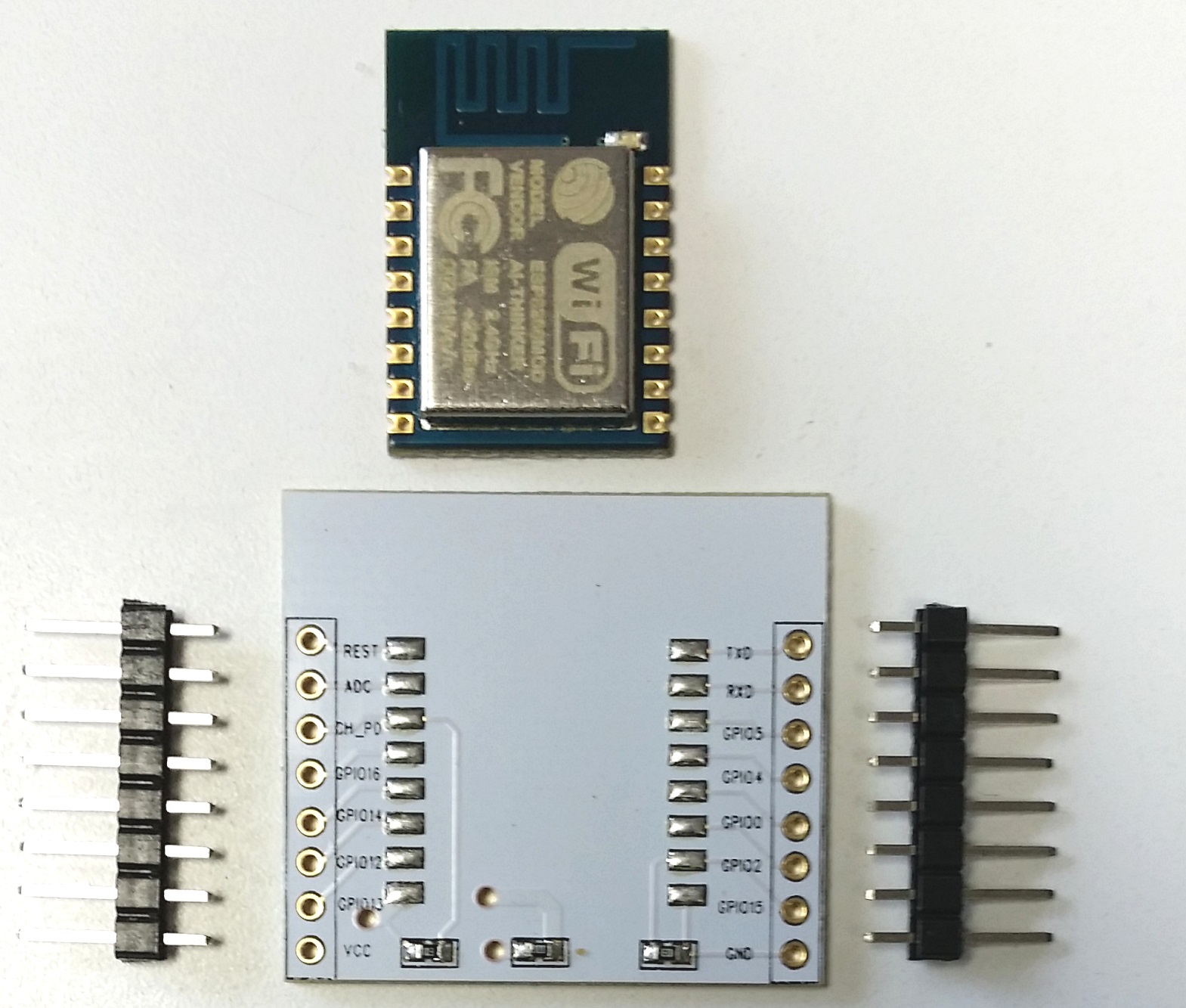
The resistor on the left is 10k pullup on CH_PD. The resistor on the right is 10k pulldown on GPIO15, not GPIO2. This board has no resistor connected to GPIO2. the center "resistor" is 0 ohms - yes it's a jumper for when there isn't a 3.3v regulator added to the underside.

I add pullups to RESET and GPIO2 on the breadboard or board I plug into.

They're a nice little board - kind of wide for one breadboard - but a great adaptor for prototyping on 0.1" perfboard.


I also miss-read that as GPIO15 shorted to 0V, thanks for pointing that out, my befuddled brain was mistakenly assuming the lettering applied to the adjacent pads on the module, as well as the pins going to the outside world. It is obvious from the pictures below, this is not the case and makes perfect sense.

I have some low standby current LDO voltage regulators on their way, so I can remove the 000 ohm link and put a regulator on the board. This might help avoid my original mistake of connecting VCC from my 3V3 FTDI adapter to the module and cooking it. (It appears that a genuine FTDI 3V3 cable has VCC at 5V... not 3V3 ooops. I should always check, never assume).

I'm also going to add any additional pullup/down resistors directly to the pins on the white PCB to keep the over all size as small as possible.
User avatar
By martinayotte
#33779
ahull wrote:I also miss-read that as GPIO15 shorted to 0V, thanks for pointing that out, my befuddled brain was mistakenly assuming the lettering applied to the adjacent pads on the module, as well as the pins going to the outside world. It is obvious from the pictures below, this is not the case and makes perfect sense.

Oviously, I did the same mistake with silkscreen alignment ... shame on me ... :?
This means the GPIO15 is properly pulled-down, but that also means no pullups on neither GPIO2/GPIO0.
Also, there is no decoupling capacitor on the VCC.
User avatar
By ahull
#33804
martinayotte wrote:This means the GPIO15 is properly pulled-down, but that also means no pullups on neither GPIO2/GPIO0.
Also, there is no decoupling capacitor on the VCC.


Good point(s). I will add the pull ups and a couple of caps when I fit the regulators.
User avatar
By Sherry Chen
#33836
rgviva wrote:Hi i just bought esp-12 module with an "IO adapter plate" - it is that white mounting breakout board that has a few smd components on top (resistors??) and a place for a component on the bottom (a voltage regulator??)

Anyone knows what are the exact schematics for this board? i googled 20 min[/img]utes could not find it :) it is easy enough to visually trace the lines, but what are the values of the resistors? and is the regulator required or optional etc

Board is similar to this:
Image

ahull wrote:
martinayotte wrote:This means the GPIO15 is properly pulled-down, but that also means no pullups on neither GPIO2/GPIO0.
Also, there is no decoupling capacitor on the VCC.


Good point(s). I will add the pull ups and a couple of caps when I fit the regulators.
You do not have the required permissions to view the files attached to this post.