- Mon May 18, 2020 2:40 pm
#87193
schufti wrote:and .. I can't find a gnd connection between the motor driver (pin 1?) and the esp board.
This is why I prefer a good picture from the real "construction" and not a - mostly euphemistic/idealized - capture as schematic; experience shows that the correlation between those two is often very weak.
Hi again!
I have tested the schema with a GND connection between DRV8833 module and ESP-12 - it makes no difference. Even more, I have noticed that even if I disconnect the pins that go to DRV8833, the signal from optocoupler is OK until I don't send HIGH to adjacent pins - GPIO12 and/or GPIO13. If there is a HIGH output signal on either of this pins, the GPIO14 switches continuously even if there is no mechanical action (covering or opening) on the optocoupler. So, from my short experience, I'd say that the ESP is defective. Once again, the components I'm using are following:
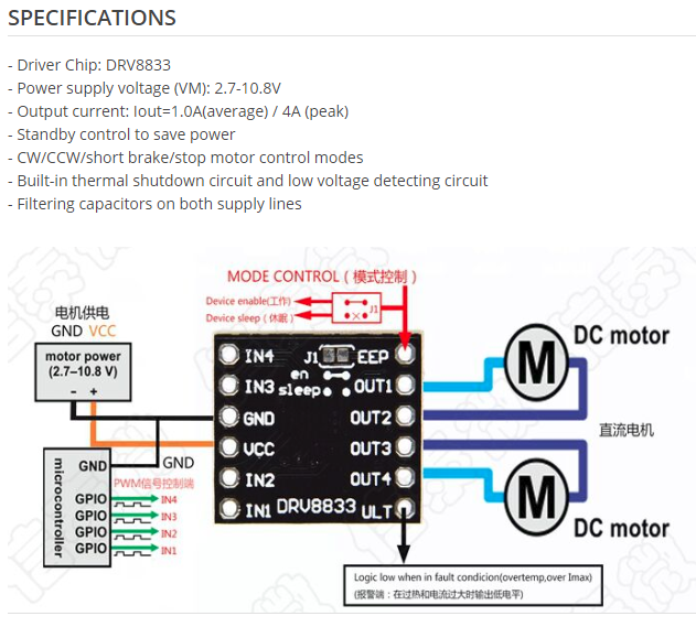
DRV8833 module -

ITR9608 - datasheet
https://www.digchip.com/datasheets/part ... 08-pdf.phpThe schema is like this -
https://drive.google.com/file/d/1NilxQe ... sp=sharingAccordingly to the bottom view of the optocoupler in it's datasheet the optocoupler is connected to GND at Cathode directly and at Emitter via 10kOhm (pins 2 and 4).
