I'm working on a project that includes an ESP-12 (just core due to space restrictions) controling an N20 motor using an ITR9608 opto interrupter. So far, I was able to program motor rotation forward and backward. Further I succeeded with reading signals from ITR9608. But when I went to combine those two parts, I felt into some errors I can't afford. Thus, asking you for help.
First of all, the power in my schema is taken from computer's USB3 and converted by an AMS1117. Am using YP-02 USB2TTL. There pins used from the YP-02 are RX, TX and GND, so the power is taken from the AMS1117.
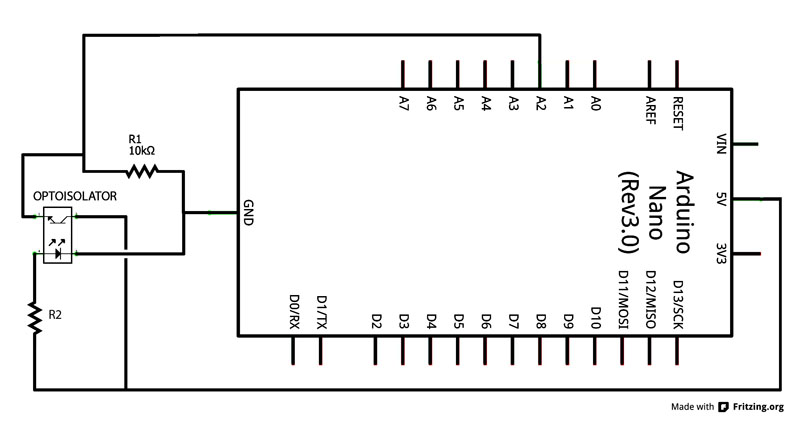
The schema for connecting opto interrupter is as follows. 3.3V through a 100Ohm goes to LED and further to the Ground. On the other side +12V is driven to Emitter and the result is pulled down through a 10 kOhm to Ground and going to ESP-12. ITR 9608 looks like it has a 1.1-1.2V Relative Forward Voltage, max 1.5V, while the current is 20mA. When connected it showed about 3V on the pin connected to the ESP-12. The schema is like taken from here:

The motor is driven by a DRV8833 Motor Driver Module Board. The board has connected to it the power 3.3V and two signal wired from ESP-12, and the motor on the other side.
The PINs used for peripherals are 12 and 13 as OUTPUT to motor and 14 as INPUT from the ITR9608. In Run mode I had connected Enable and VCC to +3.3, GND and GPIO15 to Gnd.
Software used is Arduino IDE 1.8.12 and the board defined as Generic ESS8266 Module.
I'm affraid that I have burned the PIN14 that has input from the ITR, but using another PIN (12 or 13) gave me the same result, even with the motor disconnected. I don't know exactly how to operate voltages in case that I have to INPUT a signal.
Any help is appreciated.