- Sat May 06, 2017 9:34 am
#65648
The company I work for had been manufacturing electric fence energizers for 25+ years. I didn't have a lot of involvement with that portion of the business as there was no need to change any of the designs much. I did have to do some testing when there were questions.
There are problems when it comes to measuring the output. The most obvious one is the high voltage. The next problem is the waveform. The following is what I found on the web. At work I have better samples.

Those are two traces for different energizers. One low power and one higher. The voltage is about the same. the difference is the pulse width. Those are waveforms from the fencer output not connected to a fence. The fence can have a significant impact on the waveform. The wire has capacitance to ground and that interacts with the fencer and you can get some interesting results.
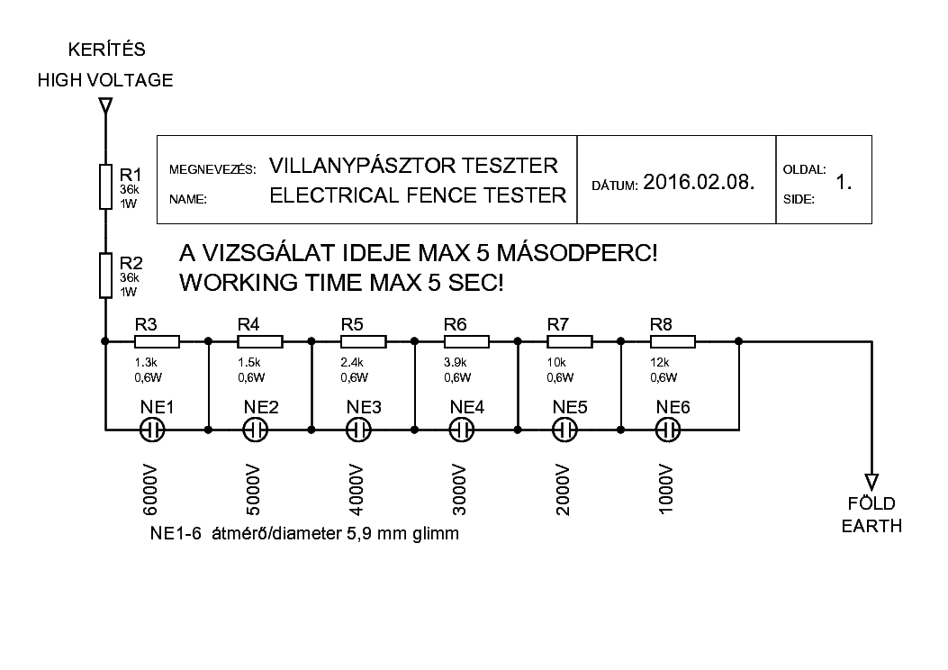
I don't recommend using a voltage divider network. You would need to get special resistors that can handle the repeated hits of that high a voltage. I don't want to go into a lot of detail. The following is used for many testers. It is simple but does not lend itself to external monitoring.

The fencer voltage indicator we had produced (we terminated the fencer line a few months ago) had a small transformer that safely converted the high voltage pulse to something more manageable for electronics to monitor. After some rectification and sampling we fed that into an ten segment LED bar-graph driver chip that was powered by a 9 volt battery. This was a handheld unit to be used along the fence line.
I have to go now, I will add more later.

