Using the new Arduino IDE for ESP8266 and found bugs, report them here

Moderator: igrr

User avatar
By Daemach
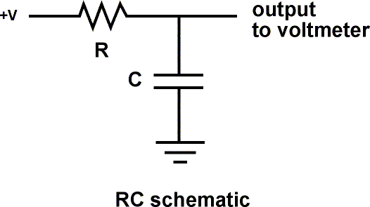
#23249 I'm trying to create a rudimentary capacitance meter using the ESP8266 and the arduino shell. It's pretty simplistic now. I'm charging a capacitor up through a 1M resistor and counting the time it takes to trigger another IO pin going high. In the following schematic I have pin 14 tied to the V+ side, and pin 12 tied to "output to voltmeter". The problem is that when pin 12 is connected, in INPUT mode, the voltage at that pin never goes above .8V - as if it's sinking to ground. If I remove the connection to pin 12, the capacitor charges up to 3V as I would expect. It's as if pinMode INPUT isn't high impedance.

Am I doing something wrong? Code is below the schematic...
Image

Code: Select allconst int chargePin = 14;
const int drainPin = 12;

unsigned long chargeTime = 0;

void setup() {
  pinMode(chargePin, OUTPUT);
  pinMode(drainPin, INPUT);
  digitalWrite(chargePin, LOW);
  Serial.begin(115200);
  delay(10);

  Serial.println();
  Serial.println();
  Serial.print("Connecting to ");
  Serial.println(ssid);
 
  WiFi.begin(ssid, password);
 
  while (WiFi.status() != WL_CONNECTED) {
    delay(500);
    Serial.print(".");
  }
 
  Serial.println("");
  Serial.println("WiFi connected"); 
  Serial.println("IP address: ");
  Serial.println(WiFi.localIP());

}

void loop() {

  unsigned long cycleStart = 0;

  // drain cap first
  pinMode(drainPin, OUTPUT);
  digitalWrite(drainPin, LOW);
  digitalWrite(chargePin, HIGH);
  Serial.print(micros()); Serial.print(" - ");
  Serial.println("Discharging...");
  delay(9000);

  cycleStart = micros();

  Serial.print(micros()); Serial.print(" - "); Serial.println("Charging!!!");

  pinMode(drainPin, INPUT);
  digitalWrite(chargePin, LOW);

  Serial.println(digitalRead(drainPin));
  while (digitalRead(drainPin) == 0) {yield();};

  chargeTime = micros() - cycleStart;

  Serial.print(micros()); Serial.print(" - "); Serial.print("Done...");
  Serial.print(chargeTime);
  Serial.println("ms");
  delay(1000);

}
User avatar
By AcmeUK
#23272 Are you refering to pin 12 of the esp8266 chip or pin 12 of your board?

I ask because the esp8266 pin 12 is the MTCK pin!

You may have a better result if you measure how long it takes to reach a specified voltage on the ADC pin.

The ADC (also called TOUT) is on pin 6 see here :- https://github.com/esp8266/esp8266-wiki/wiki/Pin-definition

Also be aware that the ADC is reported to only measure up to 1.0v. Check this out for yourself.
User avatar
By h4rm0n1c
#23305 Pin numbers in the Arduino Environment correspond to GPIO pin numbers, not to direct pin numbers on the Chip itself.
E.g 12 is GPIO12, not MTCK.

The only ADC pin is called A0, it corresponds to the TOUT pin, literally labelled as ADC on some ESP-12 breakouts.

Please refer to the ESP8266 Arduino Github project, pin functions and use are detailed in Readme.md:
https://github.com/esp8266/Arduino/blob ... /README.md
User avatar
By Daemach
#23343 I'm using the Adafruit Huzzah breakout and the arduino environment. https://www.adafruit.com/products/2471

I'm trying to avoid using the analog read function at the moment, instead just marking the time a digital IO pin crosses the voltage threshold from 0 to 1. My problem is that the pin I'm doing the digitalRead on, I assume GPIO12, doesn't seem to be in high impedance mode after setting pinMode(drainPin, INPUT);.

I might try analogRead at some point but don't like the idea of having to use a voltage divider.