Use this forum to chat about hardware specific topics for the ESP8266 (peripherals, memory, clocks, JTAG, programming)

User avatar
By rgviva
#33677 Hi i just bought esp-12 module with an "IO adapter plate" - it is that white mounting breakout board that has a few smd components on top (resistors??) and a place for a component on the bottom (a voltage regulator??)

Anyone knows what are the exact schematics for this board? i googled 20 minutes could not find it :) it is easy enough to visually trace the lines, but what are the values of the resistors? and is the regulator required or optional etc

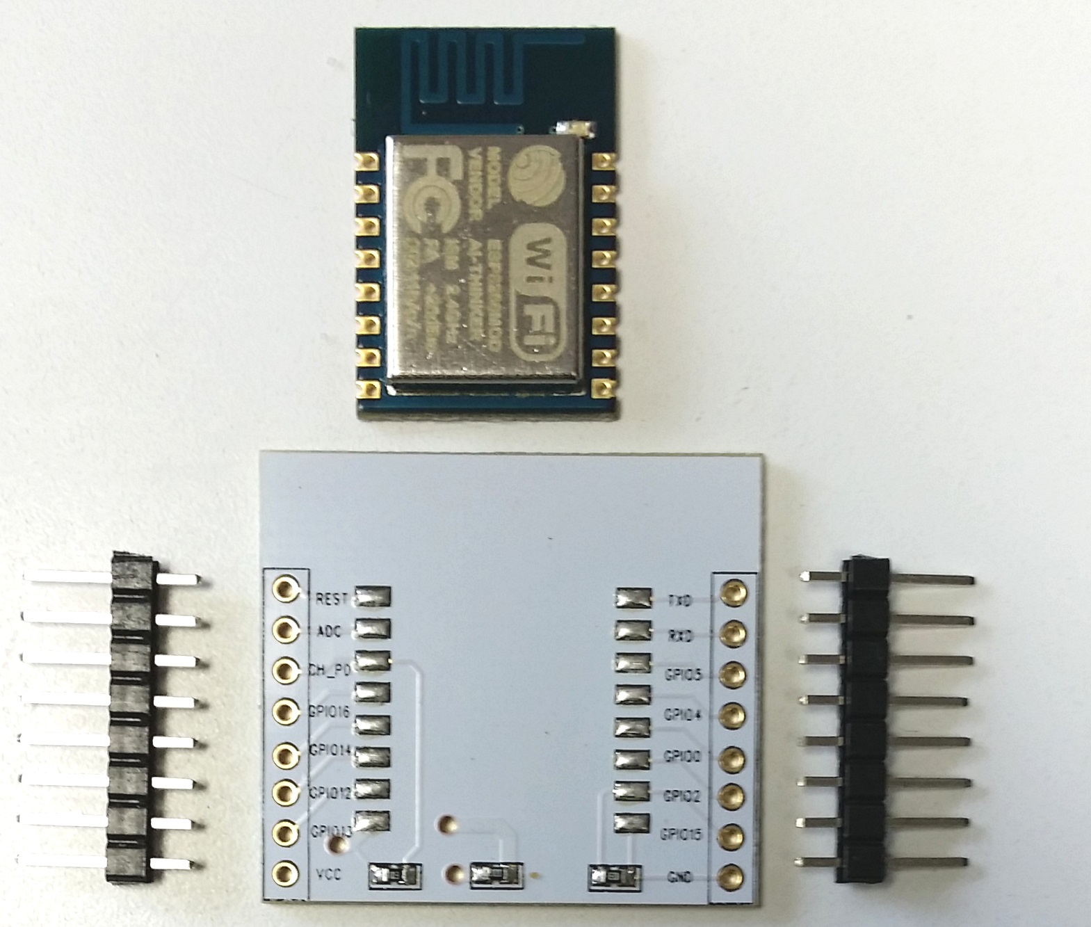
Board is similar to this:
Image
User avatar
By martinayotte
#33707 The schematic can be deducts easily just by looking at the trace in the above picture.
The left resistor is 10K pullup on CH_PD and the right resistor is 10K pulldown on GPIO2.
The middle resistor is probably a 0 ohms for optional 3V regulator that can be added at the back of the PCB.
User avatar
By Barnabybear
#33722
martinayotte wrote:The schematic can be deducts easily just by looking at the trace in the above picture.
The left resistor is 10K pullup on CH_PD and the right resistor is 10K pulldown on GPIO2.
The middle resistor is probably a 0 ohms for optional 3V regulator that can be added at the back of the PCB.


Hi, it looks like that, but I'm guessing there is something on the back that is impotant as you wouldn't expect a pull down on GPIO 2. Both GPIO 0 & GPIO 2 should be pulled up (10k ish) for normal operation. This question has been asked times before but I haven't seen this board.
In general you should be looking for:
Power
Vcc -> 3.3V
GND - > GND

Pins
CH_PD - > 3.3V (possably via 10k)
REST -> 3.3V (possably via 10k)

GPIOs
GPIO 0 -> 3.3V (possably via 10k)
GPIO 2-> 3.3V (possably via 10k)
GPIO 15 -> GND (possably via 10k)

Theres more to this than meets the eye.

"Board is similar to this:" we need a photo (link) of both sides of the board you have purchased.
User avatar
By martinayotte
#33723
Barnabybear wrote:but I'm guessing there is something on the back that is impotant as you wouldn't expect a pull down on GPIO 2. Both GPIO 0 & GPIO 2 should be pulled up (10k ish) for normal operation.

Yes, of course, I'm telling people to pullup both GPIO2/GPIO0 and pulldown GPIO15 since almost a year ... ;)
But on the picture, it shows that GPIO15 is linked to GND but the right resistor is clearly attached to GND too since it is the same trace and the other side is going to GPIO2. So, to reverse the effect of such pulldown, it needs a pullup stronger than this one ... :(
I agree that a picture of the other side can also reveal some other unknown ! :o