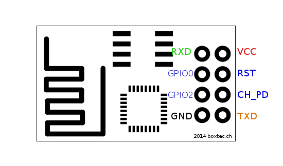
In any case, this is the problem I'm trying to sort out. I ordered the standard ESP8266 ESP-1 module,
 , which has the following pinout:
These modules come preloaded with some standard firmware that accepts AT commands, which communicates through UART. It's fairly straightforward.
However, I've been running into some issues regarding documentation for these devices, particularly with respect to the GPIO pins. In fact, I have no idea what GPIO0 and GPIO2 does on this device. What I want to do is to configure it to generate interrupts whenever the UART RX buffer is full, and an interrupt when the UART TX buffer is empty. I'd rather not waste cycles polling this device because it's rarely going to be used in my project.
That said, does anyone know how to configure the GPIO pins on this module, and what they're currently doing?
Any input is appreciated.