ichilton wrote:Also... what's a suitable regulator? - would a AMS1117-3.3 V 0.8A SOT-223 LDO work?
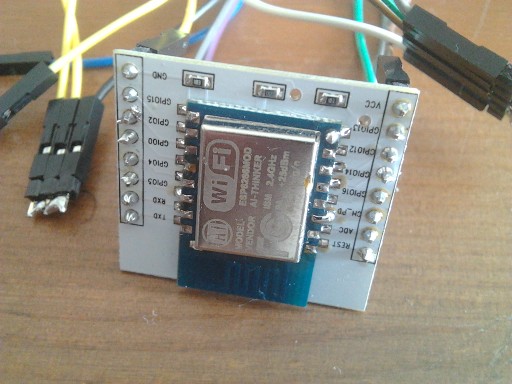
The footprint looks like SOT-89, so no, a SOT-223 regulator won't fit. I ordered some XC6203 in SOT-89 packages, but they have yet to arrive, so I can't say for sure if they'll fit.
It's pulling CH_PD up to VIN (???) via a 10k resistor - this should surely be to Vcc?
The XC6203 has a different pinout than the AMS1117, VIN & VOUT are switched.
It's connecting VIN to GPIO13?
No, it's not. The GPIO13 pin is only connected to the ESP's GPIO13 pad.
Just to avoid any confusion: GPIO13 is the pin left of the label, the hole below the label is just a via (going to the ESP's VCC pin).
It's shorting Vcc to VIN through what seems to be a 0k resistor (labelled 000 and measures direct with a multimeter)????
Anyone any idea what's going on / intended here?
It's there, so you can use the board without a LDO. If you mount a LDO, you need to remove that resistor.
They've also not left pads for capacitors next to the regulator - will it likely be unstable without them?
Yes, that's basically the only issue I have with these boards. You might get away without caps under most operating conditions, but I would still prefer if there were pads for capacitors.
I can run some tests once my LDOs arrive, but I'll probaly bodge a cap on the LDOs output side using the via next to the GPIO13 label mentioned above.
