Post topics, source code that relate to the Arduino Platform

User avatar
By Michaelo
#1821 Just to mention I tried for a couple of days to communicate with the ESP8266 and no luck...
I tried every variation of pin assignments for RESET, GPIO0 and GPIO2 and 115200, 57600, 9600 baud rates...

In my case the actual problem was using a couple of resistors to provide level shifting on the RX side of the module (TX from the Arduino)... apparently that won't work....

After hours of frustration, I finally decided to connect TX and RX directly as that was the only recourse not having components to make a proper level shift and viola! ... it worked...

Should also note I only connected 'chip select' (CH_PD) and left RESET, GPIO0 or GPIO2 floating...
Both boards were powered using the USB connected to the Arduino (no external power supply) and it worked a treat...
My module connected at 115200...

Mike
User avatar
By amaze1
#2197 I'm waiting for the "standard" ESP8266 (2x4pin connector) to come from the vendor.
In the while a couple of ESP-03 arrived (all gpios available), so I tried to talk with one of these.
Soldered some spare component leads to the smd board so I was able to insert it on the breadboard.
Tried with a Prolific USB2TTL converter and with a arduino mega 2560 (on its Serial3) as well, but unsuccesfully in both cases.
Firstly I used a resistor made 5->3.3 level converter for the TX pin and straight connection for the RX.
CH_PD was tied to 3.3Vcc (supplied by the USB2TTL converter itself, measured 3.45V).
A 1000uF capacitor was placed between 3.3VCC and GND to supply the current surges requested by the module.
Tried at 115200, 57600, 19200 and 9600 baud, with arduino mega serial monitor, sscom32E and Hyperterminal.
It seems dead, only disconnecting and reattaching the CH_PD pin to VCC I had some garbage on the terminal screen.

Tried also with a TI TXS0102 active level converter, and finally straight connection to the USB2TTL converter, but no success.

Even the flash downloader won't connect (GPIO0 tied to GND) so no firmware updates.

Do you know if GPIO2 can influence the connection ? I leaved it floating all the time.

Very discouraged :( ...
User avatar
By Michaelo
#2215 Resistor level shifting will not work...

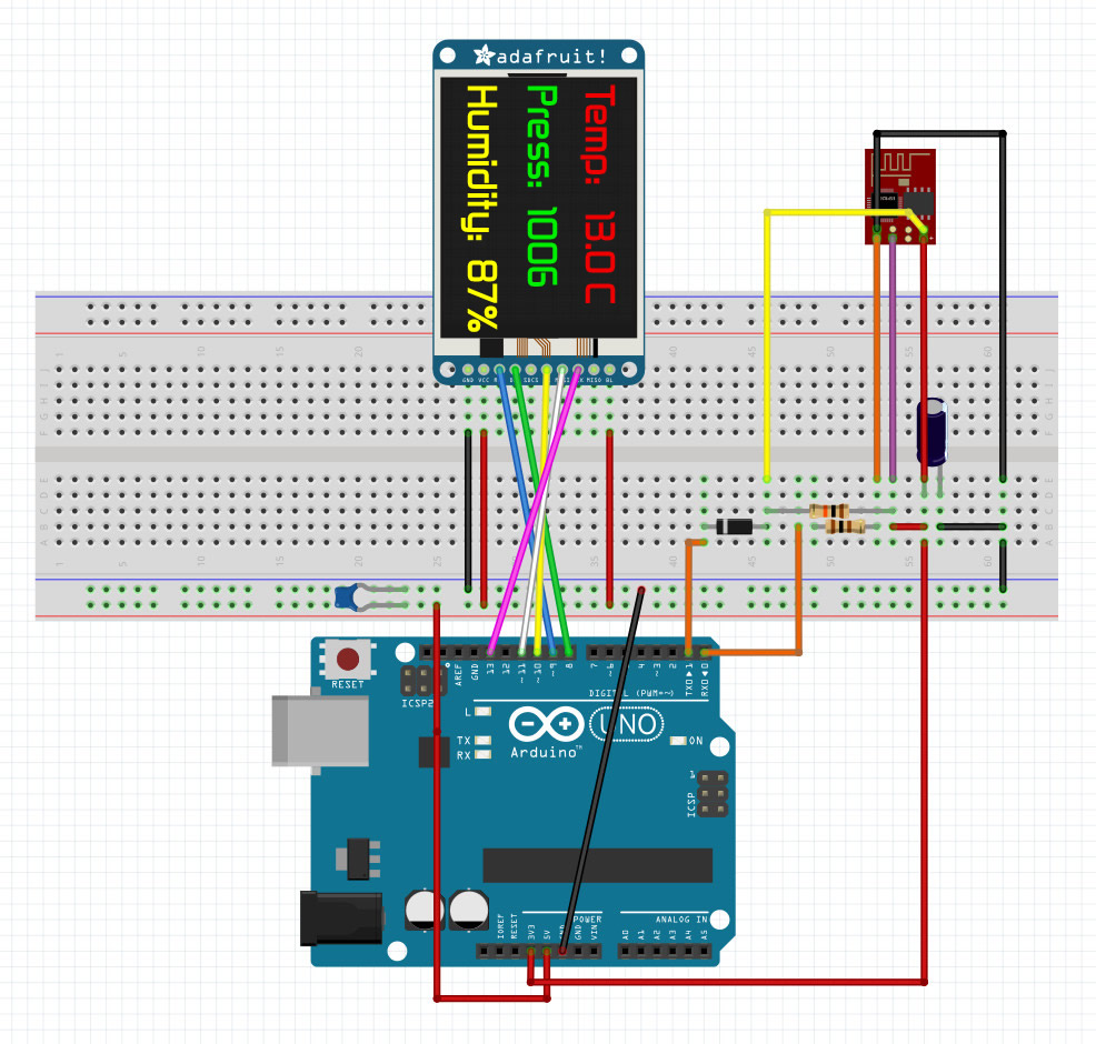
Originally I connect TX/RX directly (just to get it going), later I switched to a resistor and diode combination for protection (as in this image)

Image

I added a 100 ohm for RX side just in case (I'm paranoid about blowing my ESP82566's as they take so long to arrive)...

As I said, combining two resistors to produce a level shifter doesn't work, I tried for two days with various combinations...

The best thing to do is duplicate one of the example with the exact hardware and software using your ESP8266's and confirm they work... Then substitute one of you hardware devices at a time until you find the reason yours didn't work... that's pretty much what I did...

GPIO2 has no affect on basic communication, it can be left disconnected as too can GPIO0... just make sure CH_PD is connected to VCC...

amaze1 wrote:Even the flash downloader won't connect (GPIO0 tied to GND) so no firmware updates.

This won't work until you solve your communication issue...

Mike
User avatar
By bedenko
#2226 I have a similar problem, so i will just ask here:

i have module version2, which i (successfully?) flashed,
but when i connect with USB/UART module, i get garbage in response.

i tried both examples, "at" and "IoT_Demo", and multiple baud rates (as i see symptoms of a failed baud rate).
As i understood, baud rate of 74880 is default for "IoT_Demo" and 115200 for "at" demo.
Also CH_PD is high.
In one post i saw, that "os_printf" outputs to GPIO02, so i try to listen on that pin also with same results: garbage output.

What else can i try?

Regards

Output example:
G▒Z▒QP@XdY▒g
▒Q+kSPP
▒WJ5▒V▒DDG▒Z▒QP@XdY▒g
▒Q+kSPP
▒WJ5▒V▒DD