Your new topic does not fit any of the above??? Check first. Then post here. Thanks.

Moderator: igrr

User avatar
By mflmartin
#37431 Thanks for the info.

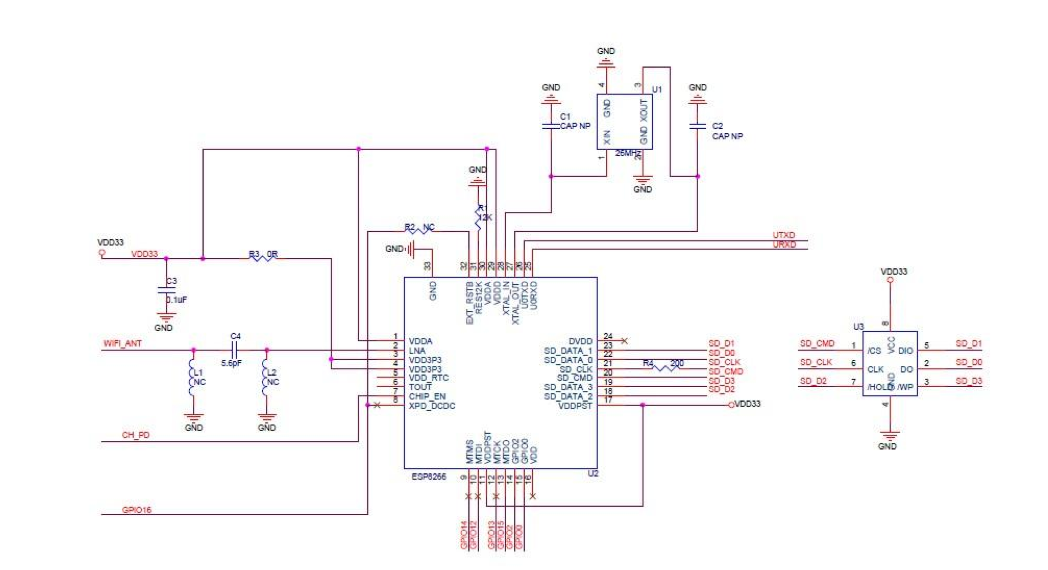
I guess i need to know the datasheet of the chip to know where to solder to extract the extra gpios for the connections:

1 CS --> IO2
2 DI(MOSI)-->IO13
3 VSS1--> GND
4 VDD-->3.3v
5 SCLK-->IO14
6 Vss2-->GND
7 DO(MISO)-->IO12

As for the GND And 3.3V, i can just connect that to my circuit as usual no? It doesnt have to pass trough the main chip, I suposse. (excuse me if the question is stupid, but I am a bit new to all this).

Thanks!
User avatar
By mflmartin
#37452 Hello. Thanks Martinayotte, I see.

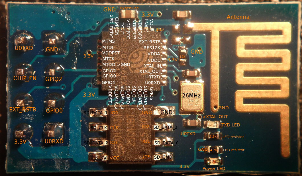
As for; GPIO14, it is MTMS in your image, GPIO13 is MTCK and the GPIO12 is MTDI, no?

It wasn't marked in your image but I found this one:

Image

Would that be correct, for those wirings?

martinayotte wrote:Image
For you question about power, I'm not sure to understand it : your power supply needs to be adequate for both the ESP and the SDCard ...


What I mean was if I can solder the SD card GND to the same GND pin that is available in the chip, and power that directly from my battery... or it is preferable to connect the SDcard GND to a row in a perfboard that is connected to GND comming from my battery or my Power supply.


Thanks!.


Martín!