
- Fri May 13, 2016 9:53 pm
#47416
Hi I need some help to optimize this pcb to fit esp12-e in a xbee form using all io's. See eagle files.
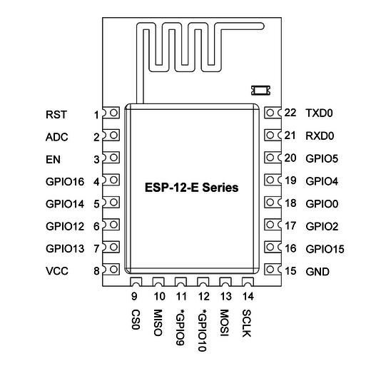
Could anyone tell me minimal pins to esp12 module work. GPIO0 low or hi to flash or run normal. CH_PD is for what? can be floating or need vcc? reset can be left floating or vcc? This pins are special so need to be carefull Some schematics show also GPIO15 need ground. is that needed?
Xbee form:
esp from:
The ideia is this one.

Any help is welcome.
Could anyone tell me minimal pins to esp12 module work. GPIO0 low or hi to flash or run normal. CH_PD is for what? can be floating or need vcc? reset can be left floating or vcc? This pins are special so need to be carefull Some schematics show also GPIO15 need ground. is that needed?
Xbee form:
esp from:
The ideia is this one.
Any help is welcome.
You do not have the required permissions to view the files attached to this post.


