posting.php?mode=post&f=30#
Required hardware:
- ESP8266 Wifi Bee (Arduino Compatible)
- Xbee USB adapter (FTDI ready)
1. Add The Board URL to Arduino IDE
Open Arduino IDE (I am using version 1.8.0).
An installation tutorial for Arduino IDE can be found here.
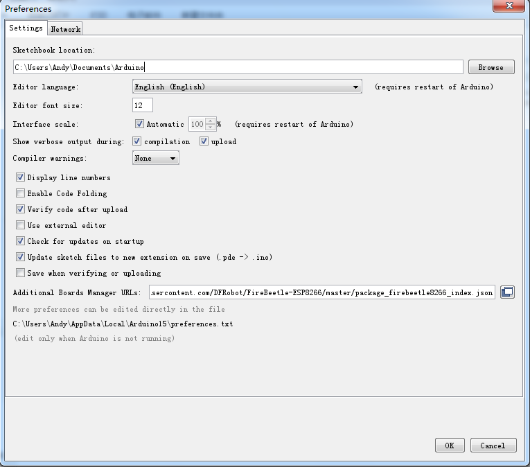
Navigate to File > Preferences and click the circled button as shown below:

Enter the following URL in the new pop-up window.
https://raw.githubusercontent.com/DFRob ... index.json
You should see this progress window:

After the input is completed, click OK.
2. Update the Board List
After adding the mainboard URL of ESP8266 (FireBeetle-ESP8266) to Arduino IDE, we need to update the board list, and use Arduino IDE to download ESP8266 libraries.
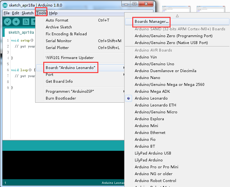
Open (Tools)-> (Development board)-> (Development board manager), as shown below:

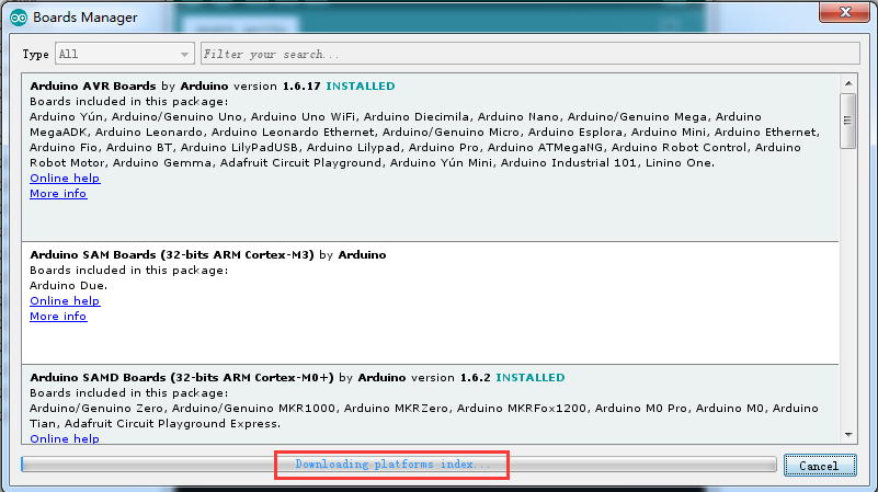
After opening the Development board manager, the board list will automatically be updated, as can be seen below:

3. Install ESP8266
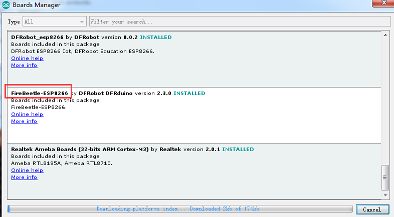
After completing the update, you should find FireBeetle-ESP8266 Mainboard options which you can then edit

Select “FireBeetle-ESP8266” and click “Install” (I have installed). The manager will automatically download the relevant libraries.

Wait for the install process to complete


After installation, you should see INSTALLED displayed in the Development board manager. You may now close it.

Close Development board manager, and the whole installation is completed.
4. Compiling a Serial Debugging Program
Now that our compilation environment is set up, we can upload a test program.
Open(Tools)->(Development board),select FireBeetle-ESP8266 mainboard, as shown in the following:
Navigate to Tools > Board and Select FireBeetle-ESP8266 from the list.

Please Note: If you haven’t installed FireBeetle-ESP8266 mainboard you will not see the board in the list, so be sure you follow the steps above to install it first!
Entering following code:
void setup() {
  // put your setup code here, to run once:
  Serial.begin(115200);
}

void loop() {
  // put your main code here, to run repeatedly:
  Serial.println("Serial Test"):
  delay(500);
}
5. Hardware Connection
Switch Wifi Bee ESP module to UART end which is the update firmware end, and insert the module on Xbee USB Adapter as shown below:

Please note the plug direction of two boards.
Set the Baud rate of download as 115200. I tried download at high Baud rate, but it always failed. Maybe FTDI chip does not support high Baud rate communication:

6. Program Download
Connect FTDI with computer, select corresponding port number and click “Download”.

Wait for the downloading to complete:

After downloading is completed, switch the Wifi Bee ESP module to BOOT end, and then re-power off and on.
Open the “Serial debugging assistant” of Arduino IDE, and you may will see the serial debugging information which is the printing information in the code as shown below:

Now we can see the print information correspond to the code.
This concludes installation of ESP8266 Arduino IDE compiling environment. You can now use it for your own projects!
Read the original ESP8266 Tutorial