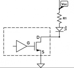
This is the best picture I found. This is what you have inside the module. See the dashed line as the actual ESP8266 chip. R1 and the led are on the module. In this picture D is the port pin. It can be an input or an output. If set for an output it can make the connection to the led be high or low. A low will put voltage across the led/R1 and the light will be on.
If you have D4 set as an input then the led will be off. If you connect a switch to D and have the switch on then you are completing the circuit with the switch and the led will turn on.