So you're a Noob? Post your questions here until you graduate! Don't be shy.

User avatar
By rudy
#72858 The circuit used in the TE291 is what I previously tried and gave me trouble. I no longer use that circuit for high speed circuits.
Image

What I did do was use the esp8266 12r Vin pin and when I power it with the usb 5volts I was able to get the address of the lcd. The vin pin will only produce about 4.3 to 4.6.


Because of the reduced voltage (not being 5v) it has brought the lcd's threshold lower so that the 3.3 volt logic level is seen as a high. I have used this technique to make things work, but only as a temporary solution.
User avatar
By sprinkfitter
#72859 Yep you are so right. The LCD likes a lot of power. Think I will try the chip you use. NLSX4373. I just order a few off ebay hope I get them soon.. Thanks for the help. I have 1 oled on the circuit think I might just put the second one. Still want to get this 5 volt thing on the i2c circuit. Thanks for all your help. Do you have a circuit built on the 3,3 v to 5v on a i2c bus line. That would be very helpful

Sprinkfitter
User avatar
By rudy
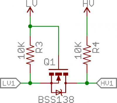
#72874 It doesn't matter what side is the 3 volt side or the 5 volt side. As long as you keep all the 3 volt signals on the same side that has the 3.3 volt power.

It doesn't matter what signal goes to which I/O pin. (SDA for example) As long as you keep the same signal across from it on the other side of the chip.

Make sure you have a high on EN the enable input. I use the same voltage as on Vcc.

I connect 3.3v to VL plus a 0.1 uF capacitor to GND.
3.3v SCL to pin 2
3.3v SDA to pin 3

On the other side I connect 5 volts to VCC, plus a 0.1uF capacitor to GND.
5v SCL to pin 7
5v SDA to pin 6
5 volts to EN

As long as pin 2 and 7 have the same signal it is right. It doesn't matter which one.

Click on image for bigger size.
You do not have the required permissions to view the files attached to this post.
User avatar
By sprinkfitter
#72890
rudy wrote:It doesn't matter what side is the 3 volt side or the 5 volt side. As long as you keep all the 3 volt signals on the same side that has the 3.3 volt power.

It doesn't matter what signal goes to which I/O pin. (SDA for example) As long as you keep the same signal across from it on the other side of the chip.

Make sure you have a high on EN the enable input. I use the same voltage as on Vcc.

I connect 3.3v to VL plus a 0.1 uF capacitor to GND.
3.3v SCL to pin 2
3.3v SDA to pin 3

On the other side I connect 5 volts to VCC, plus a 0.1uF capacitor to GND.
5v SCL to pin 7
5v SDA to pin 6
5 volts to EN

As long as pin 2 and 7 have the same signal it is right. It doesn't matter which one.

Click on image for bigger size.


Awesome I want to try that as soon as I get the chips in. Thanks big.