So you're a Noob? Post your questions here until you graduate! Don't be shy.

User avatar
By SupDoc
#76175 I found one more cable (that makes 3) still won't work. This code compiles but gives the same error messages. Thanks for not giving up on me! Here is a fresh version of the code without all the comment statements:

int pushButton = 2;

void setup() {
Serial.begin(9600);
pinMode(pushButton, INPUT);
}
void loop() {
int buttonState = digitalRead(pushButton);
Serial.println(buttonState);
delay(1);
}
User avatar
By SupDoc
#76176 This is getting weirder by the minute - tells you why I am still in the Newbie section.

I went into tools and switched the port to COM10, voila, the serial port started working!

When i got lots of weird results with the switch to the D4 (GPIO-2), I found it was putting out 3.3 v though an internal series 10 K resistor; but the pin is configured as INPUT, in software!!!

Can somebody please tell me what is going on here? It looks like the pin is set up for an internal pull-up resistor of 10 K on setup as INPUT, is that right?
User avatar
By rudy
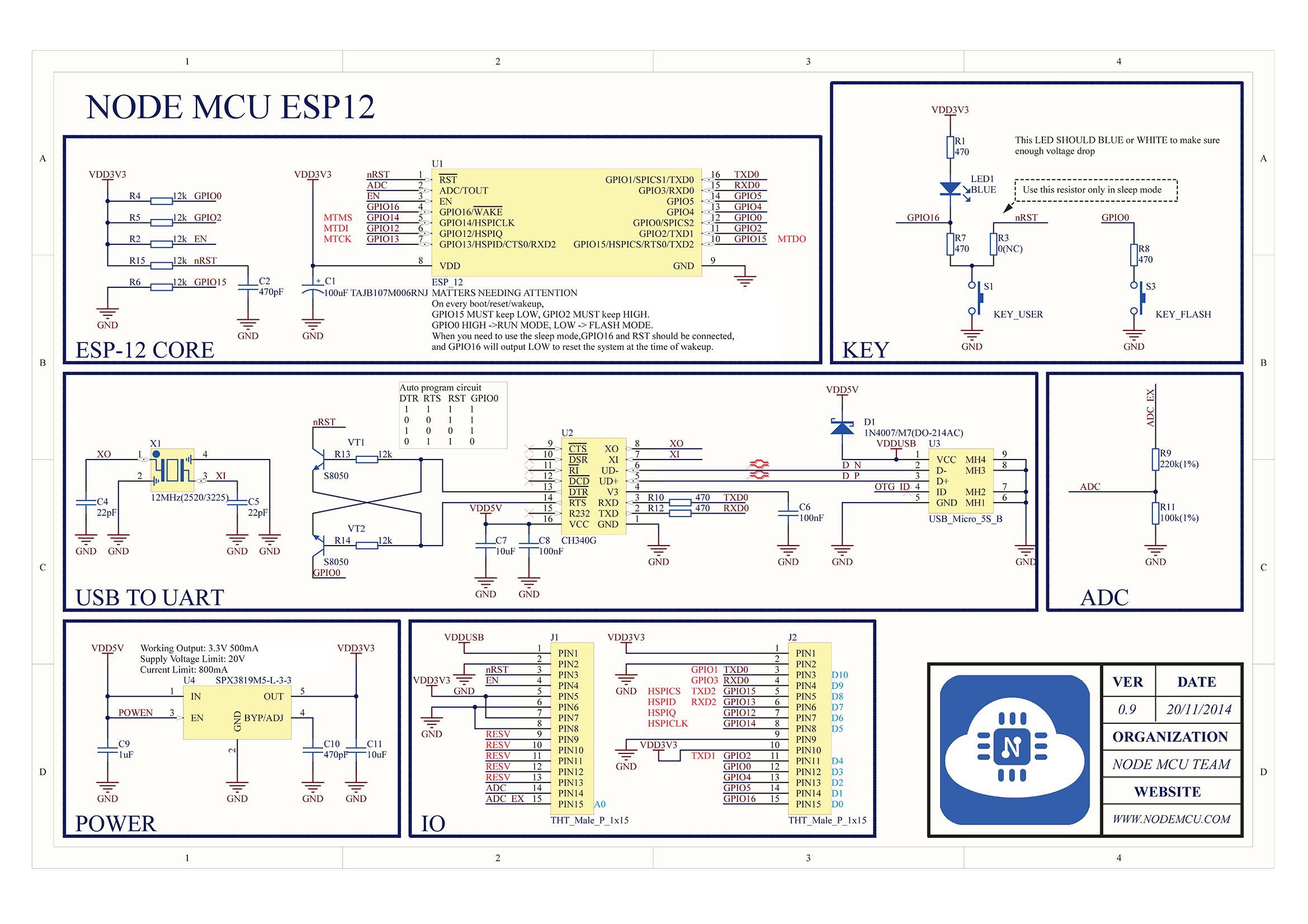
#76179 GPIO2 on the ESP-12 modules has the blue led connected to it. Maybe that is what you are seeing instead of the 10K. But if that isn't it, GPIO2 needs to be pulled high at reset, and 10k is the right value to use. It and GPIO0 and GPIO 15 determines how the ESP8266 will operate.

Typically a led and resistor are used rather than a single resistor. It is not a good practice to count on the LED to be a part of the high, but it seems to work.

EDIT

I did look for the schematic for the NODEMCU and it does show a 12K pull up resistor on GPIO2. see top left

Image

Requirements to run your code. At startup, GPIO0 =1, GPIO2 =1, GPIO15 =0.

Requirements to run bootloader to program the module. At startup, GPIO0 =0, GPIO2 =1, GPIO15 =0.
User avatar
By SupDoc
#76189 By connecting gnd-1k-(momemtary switch)-D4(GPIO2) with switch open i got 1 on the serial monitor, Measured 3.3 V. When I pressed the switch I got 0 on the serial monitor, measured 0.57 V, Which verifies the circuit in your reply.
What does configuring D4 in software to OUTPUT change this circuit? Wow this is quite different from a Genuino Uno. Is there a consistent explanation of how an ESP8266 works? I get a piece here and a bit there. It is difficult to get a handle on this beast!
Is there any way I can get a copy of the full schematic you showed in your earlier response?