So you're a Noob? Post your questions here until you graduate! Don't be shy.

User avatar
By rudy
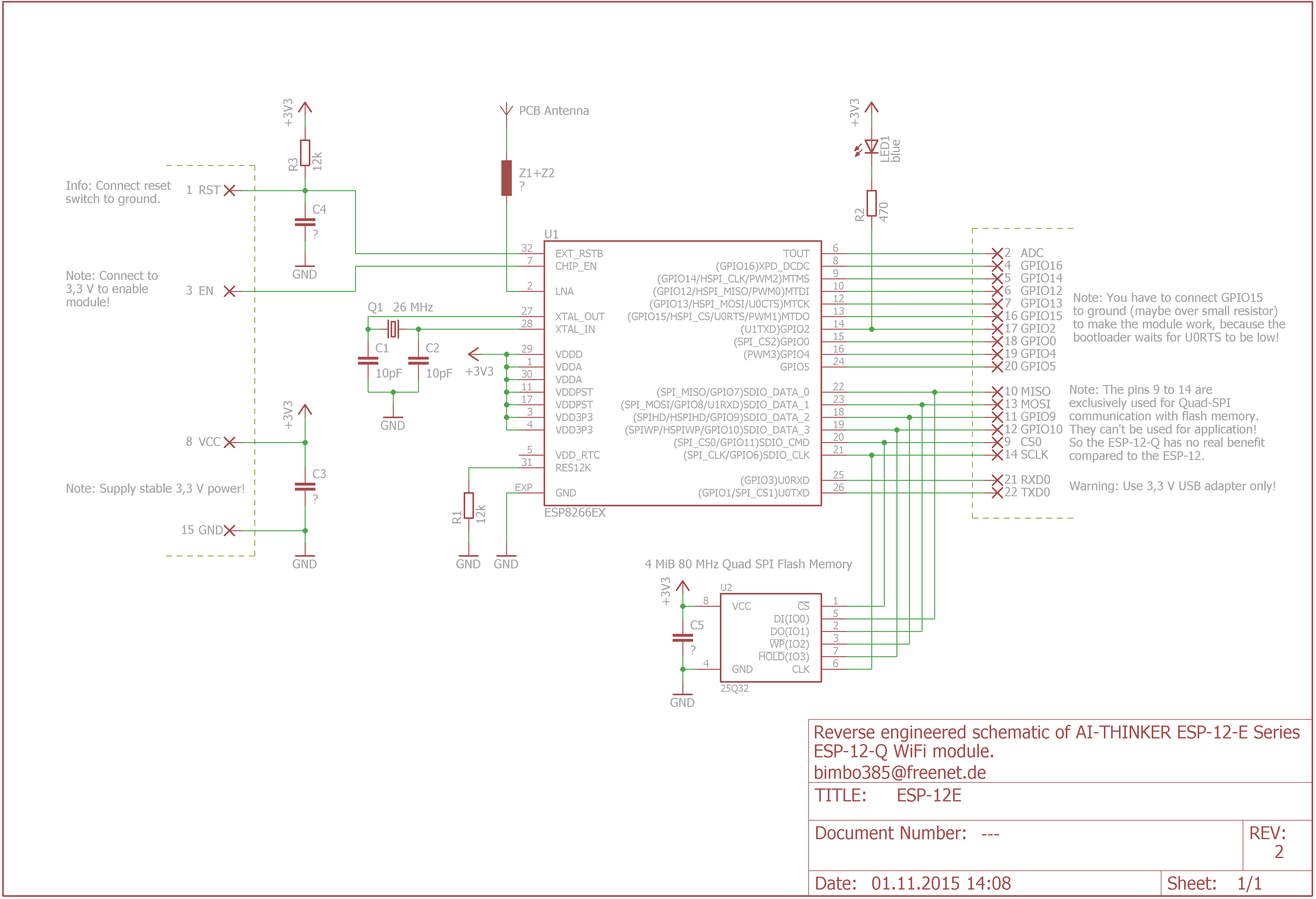
#76193 That was a full schematic of the NODEMCU boar, at least that revision. What you also want to know is what is inside the ESP-12 module. From wiki/doku.php?id=esp8266-module-family, that has a not that there is an error on the schematic. I'm never check into it.

Image

One think you do want to know is what state are the IO pins on a reset. This screwed me up. I thought the IO pins (other than 0, 2, 15) would have been inputs and high impedance. But that isn't the case. Only GPIO4 and GPIO5 are like that. Take a look at this. https://www.mjt.me.uk/posts/esp8266-gpi ... and-reset/ Go down to the summary.

While the information is scattered in different places at least it exists. Three years ago there was a lot more discoveries, and fumbling in the dark.
User avatar
By btidey
#76197 The summary table in the link is measured on a Wemos D1 so it does reflect the effects of other circuitry on that particular board which can be different from a raw ESP module or a nodeMCU. So, for example, the GPIO0 state I think may be influenced by the autoload circuitry. On a ESP12 module GPIO (which is from the bare esp8266 chip) has a weak high (~36K) during reset.

It is still a good starting point for a general understanding of the behaviour of the pins.
User avatar
By SupDoc
#76198 I'm having trouble downloading the two schematics. Can you please give me detailed instructions on how to do that or a full http or where I can download them. I tried highlighting them, copying, then pasting into WORD, which works for most things, but all I get is a corner of a highly magnified image.