Your new topic does not fit any of the above??? Check first. Then post here. Thanks.

Moderator: igrr

User avatar
By ErikLem
#76726 I recently created a circuit with a ESP-12 to connect to my doorbell ringer, so that I could perform actions whenever someone pressed the doorbell.

Image

I now use it to send a MQTT message to home assistant, which in turn takes a snapshot with the camera next to the door, sends the picture via pushbullet to my phone and also sound the wireless door ringer. Great fun, and it works like a charm :D

Now I came up with another idea to improve the circuit: I would like to connect a relay to one of the gpio pins of the ESP, so that I can also switch the regular bell on and off, for instance to turn it off during the night.

Fot that purpose I bought a Songle SRD-03VDC-SL-C relay (like these: https://www.aliexpress.com/item/5PCS-lo ... autifyAB=0). Since they're meant to be used with 3V DC I thought I could just use them right away. I tested them with a breadbord adapter at 3v (like one of these: https://www.aliexpress.com/item/Breadbo ... autifyAB=0), and it worked, so I figured it would also work if i connected it to a ESP8366 GPIO and ground.

I tried it with this code:

Code: Select all 
void setup()   {
  Serial.begin(115200);
  pinMode(16, OUTPUT);       
 
  }
 
void loop() {
   Serial.println("off");
   digitalWrite(16,LOW);         

   delay(2000);                                   
   Serial.println("on");
   digitalWrite(16,HIGH);   
   delay(2000);     

}


but it seems that it doesn't work. Googling around, I found lots of similar issues, it seems the ESP pin cannot provide enough power to trigger the relay. I also saw lots of solutions that introduced a 5v source for the relay, but since I have a 3V relay, it seems to me that it would be unnecessary (I also don't have a 5v source in my circuit and I would like to keep the parts count as low as possible).

Any idea how I could solve this problem?
User avatar
By rudy
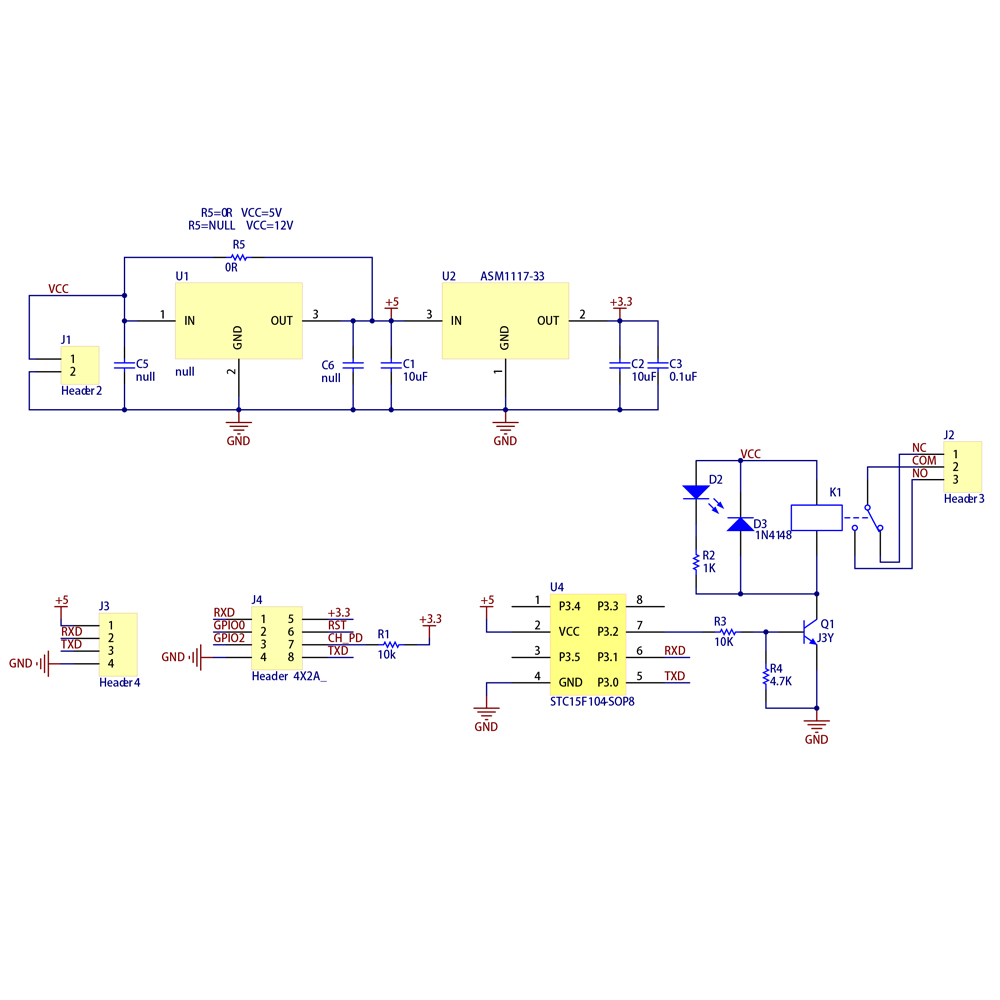
#76729 I would lower the base resistor values compared to the circuit shown above. For the same size relay the current to turn on the coil will be higher compared to a 5 volt circuit. So the drive to the transistor needs to be higher as well. I would change the 10K resistor between the port pin and the base of the transistor to 1K Ohms as a good starting point. It would be better to know the coil current, and the transistor's gain, to come up with a better base resistor, but, in general, the 1K should work.

Using mosfets will eliminate the concern about series resistors for base current (mosfets being a voltage rather than current controlled device) but you must take into account the minimum turn on voltage for the gate. (and be at minimum higher than that).
User avatar
By ErikLem
#76738 I'll immediately admit that my knowledge of electronics is not that great. :oops:

I know there are ready made shields, but I would like to integrate the relay into my own pcb, so I rather use the bare relay.

On thing i don't understand is that all samples with a transistor I find include a 5v source, including the one posted by QuickFix and the one in this circuit:

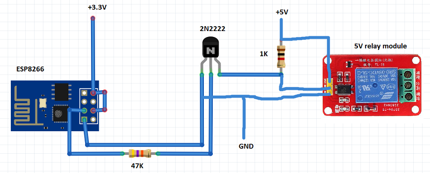
Image

Since my relay is meant to be used with 3V, I would think I don't need a 5V source. If I would take the above schematic and just connect 3.3v instead of 5V, would I be there? (Even though they do use a shield with a octocouper in this example)

The shield linked by QuickFix only seems to have a few resistors, a diode and a transistor