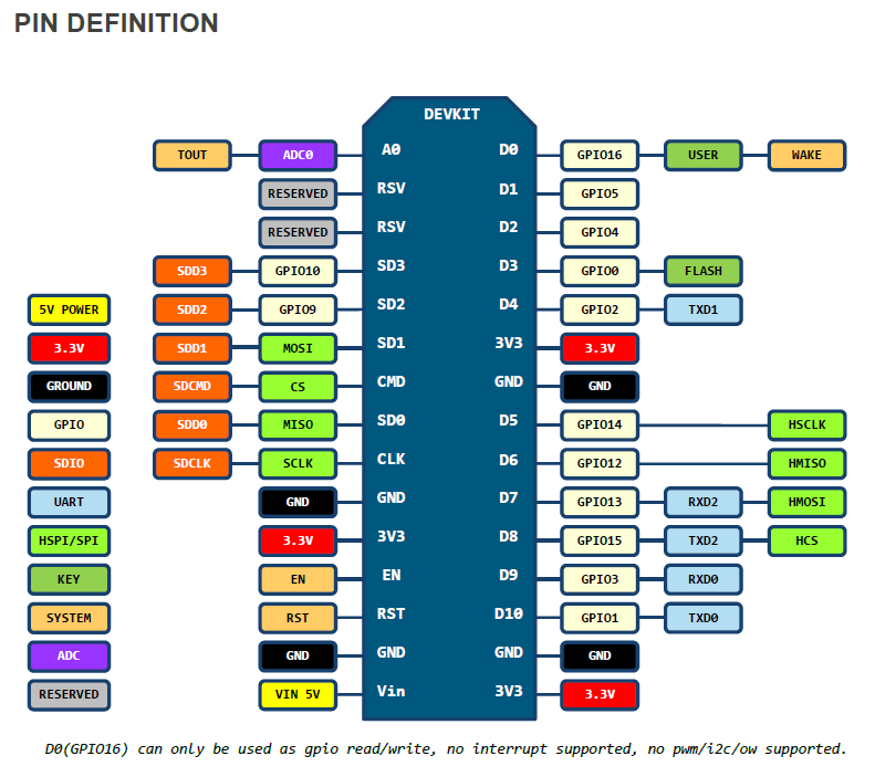
I'm adding the pin layout image I'm using as reference for support

thanks in advance for any help you could provide
Explore... Chat... Share...
Moderator: igrr

/// notes
/// the esp12e USES qio FOR THE PROGRAM FLASH
/// the places GOPI10 and GPIO9 as unavailable
/// unless the flash inside the can is removed and pins 3 and 7 lifted
/// pin 3 is wired to 7 and then to 3.3v
/// pads 3 and 7 are connected to GPIO9 and GPIO10
/// since GPIO9 and GPIO10 are now free and then set the FLASH to DIO mode
//// QIO will now not work
/// DIO mode maybe is the default for the arduino IDE NodeMCU v1 12E board
///          +--------+
///   _CS |1       8| 3.3v
///    DO |2       7| _HOLD
///   _WP |3      6| CLK
///   GND |4      5| DI
///          +--------+
#include <Arduino.h>

const int led = 2;
const int SD2 = 9;
const int SD3 = 10;
void setup()
{
//gpio_init();

 Serial.begin(112500);
pinMode(SD2,FUNCTION_3); ////GPIO on 9 and 10 is function3
pinMode(SD3,FUNCTION_3); ////GPIO on 9 and 10 is function3
pinMode(led, OUTPUT);
pinMode(SD2, OUTPUT);
pinMode(SD3, OUTPUT);
delay(1000);
Serial.print("chipid");
Serial.println(ESP.getFlashChipId());
Serial.print("chipsize");
Serial.println(ESP.getFlashChipSize());

}

void loop() {

  // put your main code here, to run repeatedly:
  digitalWrite(led, 1);
  digitalWrite(SD2, 1);
  digitalWrite(SD3, 1);

  delay(500);
  digitalWrite(led, 0);
  digitalWrite(SD2, 0);
  digitalWrite(SD3, 0);

   delay(500);

}
It takes about 20-25 seconds for home assistant c[…]
I tried to upgrade tof my sonoff basic R2 with the[…]
a problem Perhaps you want to define "Probl[…]
Rebooting your router will not give you a faster I[…]
There are no other notifications from esptool.py i[…]
Using the Arduino IDE, you'll learn how to set up […]
In this project, you will post to Twitter using an[…]
In this project, we will build a water level contr[…]
I guess I'm late, but I had the same problem and f[…]
Last night I received my first D1 Minis for a lear[…]
Although I am aware that this is an old post, I fe[…]